


10
DFEINLPGRRUTRCZSVSLHGPO
GB
At the time of shipping, the outdoor unit is charged with refrigerant.
This charge does not include the amount needed for extended piping and addi-
tional charging of each refrigerant line will be required on site. In order that future
servicing may be properly provided, always keep a record of the size and length of
each refrigerant line and the amount of additional charge by writing it in the space
provided on the outdoor unit.
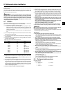
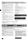
9.1. Calculation of additional refrigerant
charge
• Calculate the amount of additional charge based on the length of the piping
extension and the size of the refrigerant line.
• Use the table below as a guide to calculating the amount of additional charging
and charge the system accordingly.
• If the calculation results in a fraction of less than 0.1 kg, round up to the next
0.1 kg. For example, if the result of the calculation was 11.38 kg, round the
result up to 11.4 kg.
<Additional Charge>
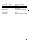
9.2. Precautions concerning piping connec-
tion and valve operation
• Conduct piping connection and valve operation accurately.
• The gas side connecting pipe is assembled in the factory before shipment.
1 For brazing to the connecting pipe with flange, remove the connecting pipe
with flange from the valve, and braze it outside of the unit.
2 The refrigerant circuit is closed with a round, close-packed packing upon
shipment to prevent gas leak between flanges. As no operation can be
done under this state, be sure to replace the packing with the hollow pack-
ing attached at the piping connection.
3 At the mounting of the hollow packing, wipe off dust attached on the flange
sheet surface and the packing. Coat refrigerating machine oil (Ester oil,
ether oil or alkylbenzene [small amount]) onto both surfaces of the pack-
ing.
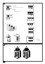
[Fig. 9.2.1]
A Close-packed packing B Hollow packing
C Valve D Packing
E Connecting pipe with flange
• After evacuation and refrigerant charge, ensure that the handle is fully open. If
operating with the valve closed, abnormal pressure will be imparted to the
high- or low-pressure side of the refrigerant circuit, giving damage to the com-
pressor, four-way valve, etc.
• Determine the amount of additional refrigerant charge by using the formula,
and charge refrigerant additionally through the service port after completing
piping connection work.
• After completing work, tighten the service port and cap securely so as not to
generate any gas leakage.
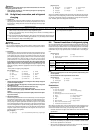
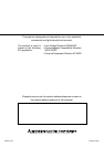
• Flare machining dimension for systems using R410A is larger than that for
systems using other types of refrigerant in order to increase the air tightness.
• Refer to the table on the below for flare machining dimensions, and follow the
regulations set forth by the local authorities.
flare machining dimension (mm)
Additional
refrigerant charge
(kg)
Liquid pipe size
Total length of
ø9.52 × 0.06
(m) × 0.06 (kg/m)
= + 3.0 kg
9. Additional refrigerant charge
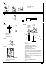
[Fig. 9.2.2] (P.3)
A Service port
For vacuuming in the refrigerant pipes on the site.
(Tightening torque 12 N·m)
B Shaft
Fully closed at the factory, when connecting the piping, and when vacuuming.
Open fully after these operations are completed.
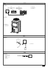
<When opening>
• Turn the shaft counterclockwise with a hexagonal wrench.
• Turn around the shaft until it stops.
<When closing>
• Turn the shaft clockwise with a hexagonal wrench.
• Turn around the shaft until it stops.
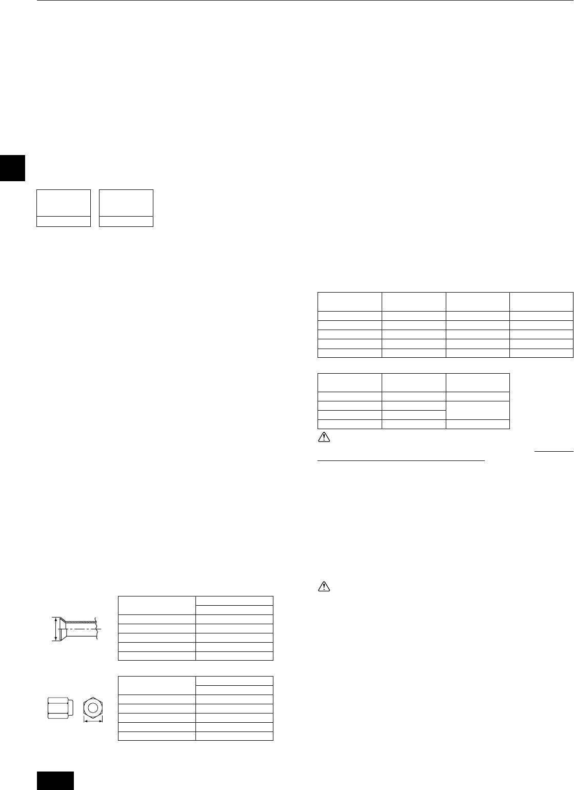
C Flare nut
Coat the flare contact surface with refrigerating machine oil (small amount of
ester oil, ether oil, or alkyl benzene) and tighten the nut with a double-ended
wrench (refer to the following table for tightening torque).
D Cap
Remove the cap before operating the shaft. Be sure to return it to the original
position after completing the operation.
E Packing
Coat both sides of the packing with machine refrigerating oil (small amount of
ester oil, ether oil, or alkyl benzene) and tighten the flange.
(Tightening torque 25 N·m)
F Connecting pipe (accessory)
Be sure to remove the connecting pipe from the valve and braze it outside the unit.
G Field piping
Braze to the connecting pipe with unoxidized brazing.
H ø9.52 mm
I ø22.2 mm
Appropriate tightening torque:
Appropriate tightening torque and its angle:
Warning:
When connecting a pipe to the service valve, be sure to use only the supplied
open-end flare nut, with small holes cut into the flats.
* Using a regular flare nut (i.e., non-supplied) will result in any water that natu-
rally flows into the nut being unable to escape.
Consequently, when the temperature becomes low, this water inside the nut
may freeze and cause damage to the joint. This, in turn, may result in a gas
leakage.
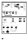
[Fig. 9.2.3]
Note:
If a torque wrench is not available, use the following method as a standard;
When you tighten the flare nut with a wrench, you will reach a point where
the tightening torque will abruptly increase. Turn the flare nut beyond this
point by the angle shown in the table above.
Caution:
•Always remove the connecting pipe from the valve and braze it outside
the unit.
-Brazing the connecting pipe while it is installed will heat the valve and cause
trouble or gas leakage. The piping, etc. inside the unit may also be burned.
• Use ester oil, ether oil or alkylbenzene (small amount) as the refrigerat-
ing machine oil to coat flares and flange connections.
- The refrigerating machine oil will degrade if it is mixed with a large amount of
mineral oil.
•Keep the valve closed until refrigerant charging to the pipes to be added
on site has been completed. Opening the valve before charging the re-
frigerant may result in unit damage.
• Do not use a leak detection additive.
[Fig. 9.2.4]
A Example of closure materials (field supply)
B Fill the gap at the site
Make sure to seal-off the space around areas where the wires and refrigerant
pipes enter the unit to ensure that small animals, rainwater, or snow cannot enter
the unit through such openings and cause damage to the unit.
A
B
flare nut size (mm)
Outer diameter of
copper pipe (mm)
ø9.52
ø12.7
ø15.88
ø19.05
ø25.4
Shaft (N·m)
5
9
15
15
30
Size of hexagonal
wrench (mm)
4
4
6
6
10
Cap (N·m)
22
20
25
25
40
Outer diameter of
copper pipe (mm)
ø9.52
ø12.7
ø15.88
ø19.05
Tightening torque
(N·m)
35 - 42
50 - 57.5
75 - 80
100 - 140
Tightening angle
(°)
60 to 90
30 to 60
20 to 35
outer diameter
ø6.35
ø9.52
ø12.7
ø15.88
ø19.05
dimension B
R410A
17.0
22.0
26.0
29.0
36.0
outer diameter
ø6.35
ø9.52
ø12.7
ø15.88
ø19.05
dimension A
R410A
9.1
13.2
16.6
19.7
24.0