


86
A N E
T
(Y)
(W) (R) (O)
(BR)
5A
A
POWER
SUPPLY
N
E
Fuse(5A)
Tie-wrap
Wiring has to be changed when
a 200,230 or 240V power is used.
Tie-wrap
TRANSFORMER
Transmission
TERMINAL-BLOCK
FOR TRANSMISSION
TERMINAL-BLOCK
OF POWER SUPPLY
200
220
230
240
BACK
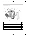
ACTIVE
BYPASS
POWER
ON/OFF
DUAL
CENTRAL
AHEAD
ENGAGED
GROUP
ACTIVE BYPASS
GROUP
SELECTION
PROGRAM
TIMER
CONTROLLER
OPERATION
DUAL CENTRAL
12345678910
10 9 8 7 6 5 4 3 2 1
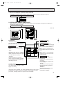
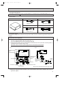
To adaptor's
terminal-block
Centralized remote
controller
Non-polar,
two-wire cable
To adaptor's
terminal-block
Power supply board box
BACK
ACTIVE
BYPASS
POWER
ON/OFF
DUAL
CENTRAL
AHEAD
ENGAGED
GROUP
ACTIVE BYPASS
GROUP
SELECTION
PROGRAM
TIMER
CONTROLLER
OPERATION
DUAL CENTRAL
12345678910
10 9 8 7 6 5 4 3 2 1
Dip switch
SW17
Centralized
remote controller
Power supply
board
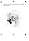
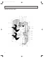
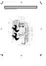
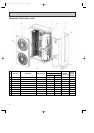
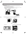
5-3 Connection method
(1) Connections in the power supply cord.
1. Connect the power supply cord to the power supply terminal-block and fix it in-place with a tie-wrap.
Connect a single phase 200V AV (220, 230, 240V) to
A N.
As E is the GND terminal, be sure to ground the earth wire.
2. Connect the transmission line to the transmission terminal-block and fix it in-place with a tie-wrap. Use a Ø1.6
(AWG 14) or above two-wire cable for the transmission line.
CAUTION : Never connect the power supply cord to the transmission terminal-block.
(2) Connection method of centralized remote controller and power supply board.
1. Connect the centralized remote controller and power supply board with a non-polar, two-wire cable.
2. Wiring diagram 3. Be sure to set the maximum address number with the
dipswitch SW17 on the centralized remote controller.
OC120--3.qxp 24/6/97 1:05 AM Page 86