


62
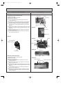
NOTE1 : Install the relay box where it can be serviced easily.
NOTE2 : For control circuit wiring, use a wire of No. 14 AWG or a control cable according to the power supply of control
circuit.
NOTE3 : When the power supply of the control circuit is 220/240V AC,
● Do not connect the control circuit wire to the remote controller cable directly.
● Do not place the control circuit wire and the remote controller cable into the same conduit.
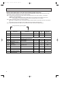
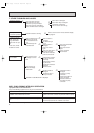
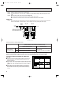
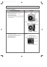
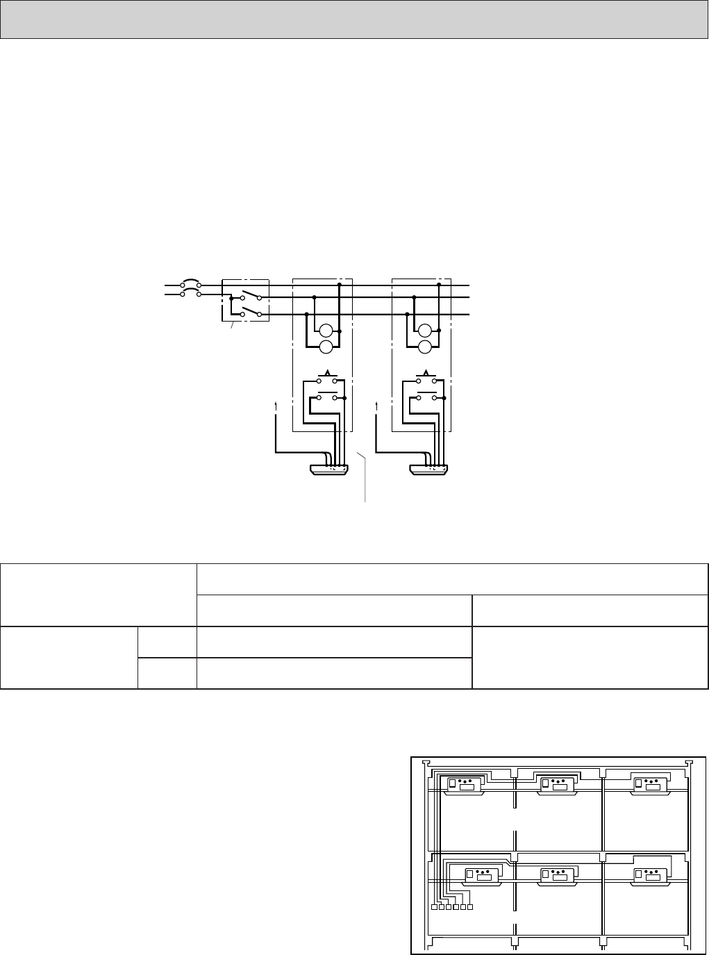
4-2 Basic wiring
Caution : Before starting all units simultaneously by the remote ON-OFF switch, be sure to connect a sequence-start timer
into the remote ON-OFF circuit. Otherwise, a rush of starting current may damage the power supply.
w1 After all units start together, if SW2 is turned OFF, each unit can be individually stopped by each remote controller.
w2 After all units stop together, if SW2 is turned OFF, each unit can be individually started by each remote controller.
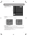
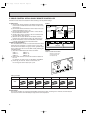
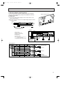
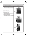
5. INDIVIDUAL CONTROL BY GROUPING THE REMOTE CON-
TROLLERS
● Grouping the remote controllers allows individual control and cen-
tralized monitoring of units installed in different places without a
special control board.
● Remote control cables are extendable up to 500m. When the cable
length exceeds 12m, use the double-insulated two-core cable such
as Belden 9407. Also, the cable thickness must be No. 22 AWG or
above.
● When gathering the power ON/OFF switches of air conditioners
near the remote controllers, you should also install the power
ON/OFF switch near each unit to prevent electric trouble during
servicing.
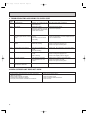
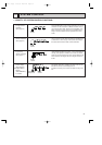
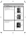
4-3 Switch function of remote ON-OFF switch
SW1
(Switches between
remote ON and OFF.)
ON
(Start)
OFF
(Stop)
All units start together.
Individual control is not available.
All units stop together.
Individual control is not available.
SW2
(Switches between remote ON-OFF and individual control)
ON
(Remote ON-OFF control)
Each unit can be controlled by each
remote controller.
Remote ON-OFF switch is not available.
OFF
(Individual control)
w1
w2
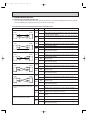
Power
supply
Remote
ON/OFF
switch
No.1 unit
relay box
No.2 unit
relay box
Next unit
T
X2 X2
T
Glow switch or pilot lamp can be
combined to easily identify the
on-off mode of SW1 and SW2.
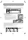
To
No.1
unit
To
No.2
unit
Timer adapter cables
Remote controller
T
X2
SW
1
SW2
T
X2
Remote
controller cable (2-core)
Remote controller
OC120--2.qxp 24/6/97 12:33 AM Page 62