


69
OPERATING PROCEDURE PHOTOS
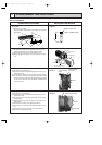
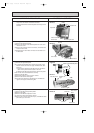
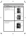
1. Electrical parts
(1) Remove top panel (3 screws in front, 2 screws in rear)
(2) Remove cover panel (1 screw).
The panel is anchored by clicks to the side panel.
Remove by pulling towards you.
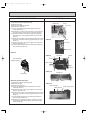
(3) Remove cover panel (1 screw).
The panel is clasped on the right and left sides. After remov-
ing the screw, pull the panel down and remove it by pulling
towards you.
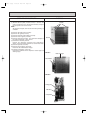
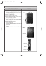
2. Fan motor
(1) Remove front panel (3 screws).
Open the panel to a 45 degree angle and lift to remove. The
panel is clasped at three points on the left side.
(2) Remove propeller (1 set nut).
(3) Remove fan motor (3 screws).
Remove lead connectors.
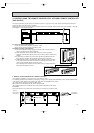
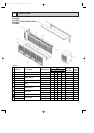
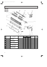
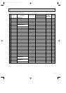
13-5 Outdoor unit (PUH24EK)
Screws
Panel cover
Photo 1
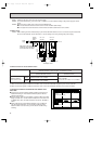
Compressor protector
Run capacitor
52C relay
Terminal block
Screws
Photo 2
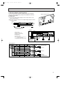
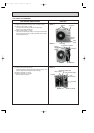
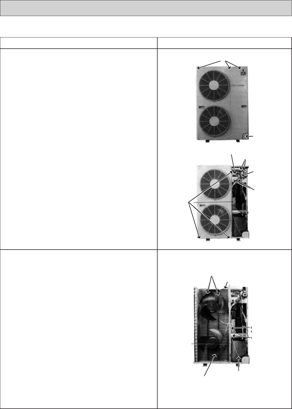
Motor support
Separator support place
High-pressure
switch
Valve bed
Crank case heater
Propeller fan
Propeller
nut
Photo 3
OC120--3.qxp 24/6/97 12:57 AM Page 69