


19
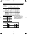
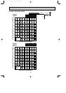
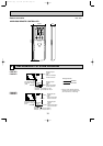
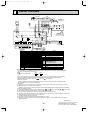
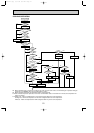
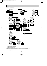
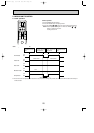
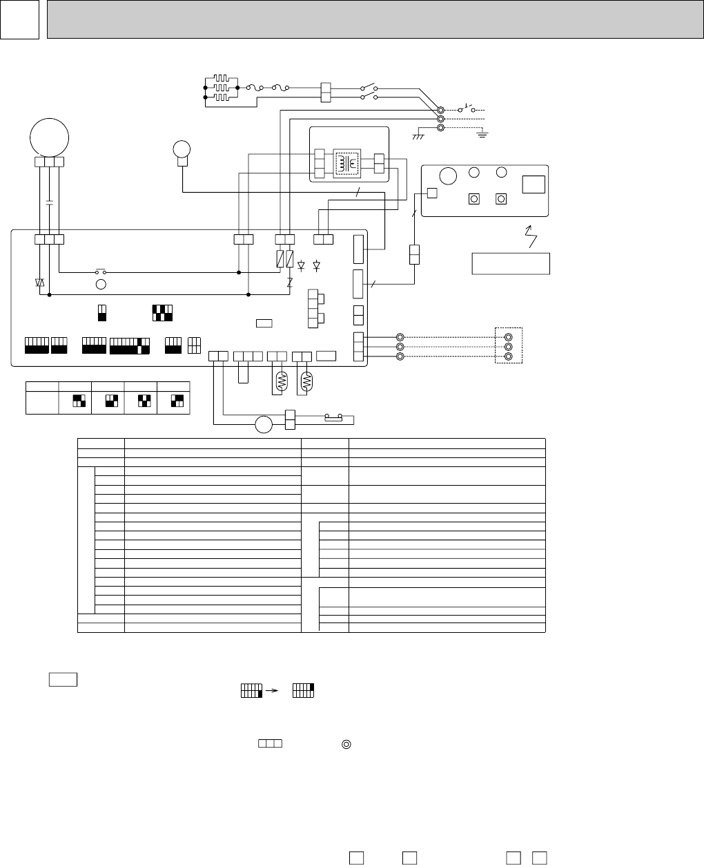
WIRING DIAGRAM
7
MODELS PKH18FL, PKH24FL, PKH30FL, PKH36FL
WIRING DIAGRAM
GR
L1
L2
POWER SUPPLY
~(1PHASE)
AC208/230V 60Hz
GROUND
3
LED(HOT ADJUST)
LED(RUN INDICATOR)
LED1
LED2
WIRELESS REMOTE CONTROLLER
W.R
FS1,2
THERMAL FUSE
88H
HEATER CONTACTOR
HEATER THERMAL SWITCH
HEATER
26H
H
HEATER
12 312 312 3
36FL
OFF
ON
30FL
OFF
ON
MODELS 24FL
12 3
ON
OFF OFF
ON
SW7
18FL
ON
OFF
LED(DC5V POWER)
X4
RELAY(FAN MOTOR)
LED1
LED2
LED(DC12V POWER)
SW9
SWITCH(MODEL SELECTOR)
F1,F2
VARISTORZNR
SYMBOL NAME
I.B
INDOOR POWER BOARD
INDOOR CONTROLLER BOARD
CN2L
SW1
SW2
SW6
FC
CONNECTOR(LOSSNAY)
SWITCH(FUNCTION SELECTOR)
SWITCH(ADDRESS SELECTOR)
SWITCH(MODEL SELECTOR)
FAN PHASE CONTROL
P.B
CN51
CONNECTOR(CENTRALLY CONTROL)
SW3
SWITCH(EMERGENCY OPERATION)
SW5
SWITCH(MODEL SELECTOR)
SW7
SWITCH(TWIN/TRIPLE SELECTOR)
SW8
SWITCH(OPTION)
BZ
TB2~TB6 TERMINAL BLOCK
ROOM TEMPERATURE THERMISTOR
RT1
RT2
PIPE TEMPERATURE THERMISTOR/LIQUID
W.B
WIRELESS REMOTE CONTROLLER BOARD
BUZZER
SWITCH(HEATER ON/OFF)
SW1
SWITCH(COOLING ON/OFF)SW2
RECEIVING UNIT
RU
NAMESYMBOL
VANE MOTOR
MV
FAN MOTOR
MF
CAPACITOR(FAN MOTOR)
C
12
OFF
ON
1542
231
2341
165432
1432
165432
10987654321
ON
OFF
ON
OFF
ON
OFF
RG79J693H02
321
9
ORN
YLW
1
2
TB4
3
BRN
TB3
OUTDOOR UNIT
1
2
TRANSMISSION WIRES DC12V
3
9
REMOTE
W.R
CONTROLLER
CNB
W.B
LED1
LED2
BZ
RU
SW1 SW2
ON
123456
OFF
OFF
123456
ON
NOTES:
1.Since the indoor fan motor(MF)is connected with 230V power,if 208V power is used,change the dip switch(SW8)on
the indoor controller board as shown in fig:*1.
fig:*1
Indoor fan motor(MF)for 208V.
2.Since the outdoor side electric wiring may change be sure to check the outdoor unit electric wiring for servicing.
3.Indoor and outdoor connecting wires are made with polarities, make wiring matching terminal numbers.
4.Symbols used in wiring diagram above are, :Connector, :Terminal block.
5.Emergency operation
If remote controller or microcomputer fails but there is no other trouble emergency operation is possible by setting
dip switch(SW3<I.B>) on the indoor controller board.
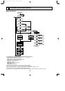
[Check items]
(1) Make sure that no other trouble exist in the outdoor unit.Trouble with the outdoor unit prevents emergency operation.
(2) Make sure that there is no trouble with the indoor fan.
Emergency operation will be continuous run with the power ON/OFF(ON/OFF with the remote controller is not possible).
[Emergency operation procedure]
(1) Set the dip switch(SW3<I.B>)on the indoor controller board to 1 on and 2 off for cooling and 1 • 2 on for heating.
(2) Turn on outdoor unit side circuit breaker,then indoor unit side circuit breaker.
(3) During emergency operation indoor fan runs at high speed but auto-vane does not work.
(4) Thermostat will not function.Cold air blows out for defrosting during heating thus do not operate defrosting for a long time.
(5) Emergency cooling should be limited to 10 hours maximum
(the indoor unit heat exchanger may freeze).
(6) After every emergency operation,set all dip switches(SW3<I.B>) to OFF.
(7) Movement of the vanes does not work in emergency operation,therefore you have to slowly set them manually to the
appropriate position.
SW8
SW8
H
FS1FS2
88H
TB2
26H
BWN
YLW
8
88H
5
6
GRY
7
GRY
RED
BLUBLU
64
35
RED
2
1
12
HEATER
CN24
(YLW)
6
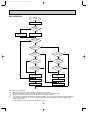
[LEGEND]
2
1
3
2
1
3
2
1
2
1
312 12
12
4
3
2
1
213131
SW3 SW9
SW7
SW6
SW1
SW8
SW5
RT2
RT1
F2
F1
SW2
CN51
CENTRALLY
CONTROL
(WHT)
CN40
REMOCON
POWER
LED1 LED2
CN2L
LOSSNAY
ZNR
OUT
DOOR
CN30
WHT
BLK
CN2D
(WHT)
GRN/YLW
RED
BLU
RED
BLU
P.B
TRANS
(DC13.1V)
CN2S (WHT)
CNSK(RED)
I.B
MF
C
135
FC
MV
X4
X4
WHT
RED
BLK
WHT
BLK
FAN
(WHT)
INTAKE
CN20
(RED)
POWER
CNDK
(WHT)
POWER
CND
(RED)
WIRELESS
CN90
(WHT)
REMOCON
CN22
(BLU)
PIPE
CN21
(WHT)
VANE
CN6V
(WHT)
DRAIN
CN31
(WHT)
243˚F ,10A(18,24FL)/16A(30,36FL)
FUSE(6A/250V)
(32˚F /15kΩ, 77˚F /5.4kΩ DETECT)
(32˚F /15kΩ, 77˚F /5.4kΩ DETECT)
(AC208/230V)
(BLU)
The drawing has been revised as some errors in
WIRING DIAGRAM have been modified.
The former drawing number is RG79J693H01.
OC276-A-1.qxp 03.11.25 9:04 AM Page 19