


6
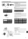
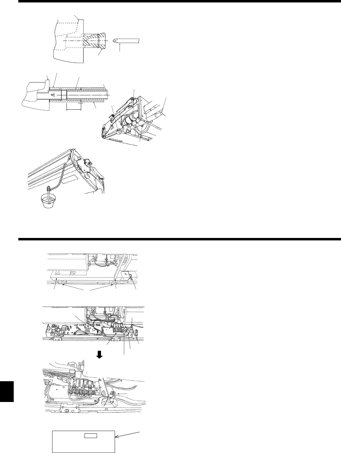
5. Drainage piping work
6. Electrical work
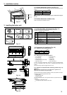
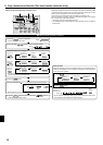
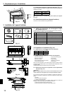
• For left side tubing, be sure to insert the rubber plug into the right drain port. (Fig.
5-1)
• Use VP-20 (O.D. ø26 (1”) PVC TUBE) for drain piping and provide 1/100 or more
downward slope.
• After completion of work, check that correct drain is available from the outfl ow
port of the drain tubing.
Drain pan
Plug
Insert the driver etc.in the plug deeply.
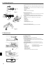
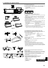
Installing procedures (Fig. 5-2)
1. Attach the joint socket
supplied with the unit to the drain port on the unit with a
vinyl chloride adhesive.
2. Fasten the socket cover
supplied with the unit to the joint socket
.
3. Attach the fi eld drain tubing (VP-20) to the joint socket
with a vinyl chloride
adhesive.
4. Wrap the drain tubing cover
supplied with the unit. (Seam taping)
Drain pan
Drain tubing
Socket cover
Joint socket
Drain tubing cover
Insertion length 1-15/32 in. (37mm)
5. Check for correct drainage. (Fig. 5-3)
* Fill the drain pan with water of about 1/4 gal (1 L) from the air outlet.
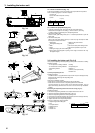
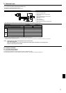
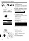
6.1. Electric wiring
Wiring procedures
1. Remove the tapping screw
then remove the beam.
2. Remove the (2) tapping screws
then remove the electric part cover
.
3. For radio frequency interface.
Connect the electric cord of radio frequency interface securely to CN105 (RED)
on indoor controller board.
For wired remote controller
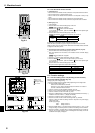
Connect the electric wires securely to the corresponding terminals (Fig. 6-1)
4. Replace the removed parts.
5. Tie the electric wires with the local wiring clamp located in the right side of the
junction box.
Cover
Grounding cable connector
Set screws (2 pcs)
Terminal block for wired remote controller
Set screws (Beam)
7
Secure with the wiring clamp.
Wiring clamp
Indoor controller board
Wire service entrance
Terminal block for indoor and outdoor units connection
CN105
(RED)
7
Fig. 5-1
Fig. 5-2
Fig. 5-3
Fig. 6-1
Fig. 6-2