


10
7. Test run
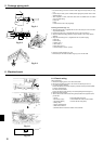
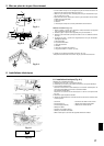
7.1. Before test run
► After completing installation and the wiring and piping of the indoor and
outdoor units, check for refrigerant leakage, looseness in the power sup-
ply or control wiring, wrong polarity, and no disconnection of one phase
in the supply.
►
Use a 500-volt megohmmeter to check that the resistance between the
power supply terminals and ground is at least 1.0 MΩ.
► Do not carry out this test on the control wiring (low voltage circuit) termi
-
nals.
Warning:
Do not use the air conditioner if the insulation resistance is less than 1.0 MΩ.
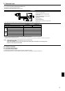
7.2. Test run
Refer to the installation manual that comes with each remote controller for details.
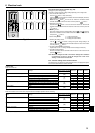
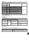
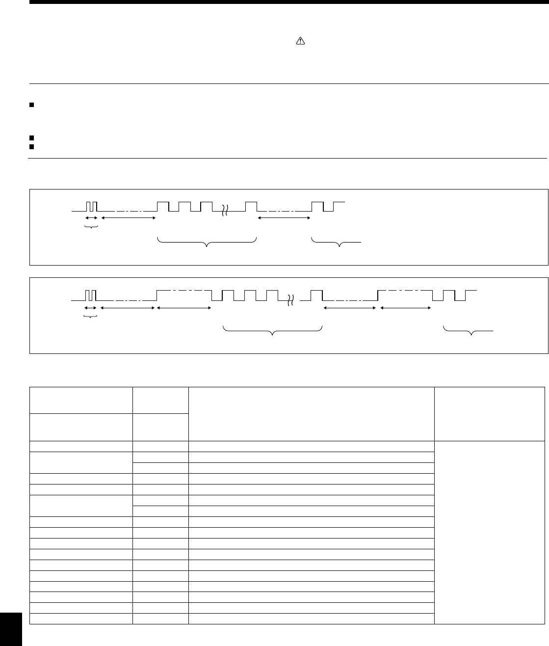
• Refer to the following tables for details on the check codes. (IR wireless remote controller)
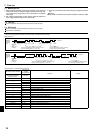
[Output pattern A]
[Output pattern A] Errors detected by indoor unit
IR wireless remote controller
Wired remote
controller
RF thermostat
Symptom Remark
Beeper sounds/OPERATION
INDICATOR lamp blinks
(Number of times)
Check code
1 P1 Intake sensor error
2
P2 Pipe (TH2) sensor error
P9 Pipe (TH5) sensor error
3 E6, E7 Indoor/outdoor unit communication error
4 P4 Drain sensor error / Float switch connector open
5
P5 Drain pump error
PA Forced compressor error
6 P6 Freezing/Overheating protection operation
7 EE Communication error between indoor and outdoor units
8 P8 Pipe temperature error
9 E4 Remote controller signal receiving error
10 — —
11 — —
12 Fb Indoor unit control system error (memory error, etc.)
No sound E0, E3 Remote controller transmission error
No sound E1, E2 Remote controller control board error
No sound – – – – No corresponding
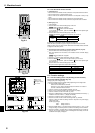
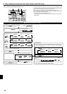
7.3. Self-check
Refer to the installation manual that comes with each remote controller for details.
RF thermostat is not established.
OPERATION
INDICATOR
lamp blinking
pattern
Beep Beep Beep Beep Beep Beep Beep
Off
Approx. 2.5 sec.
On
Approx. 3 sec.
On
0.5 sec.
On
0.5 sec.
On
0.5 sec.
On
0.5 sec.
Off
Approx. 2.5 sec.
On
Approx. 3 sec.
On
0.5 sec.
On
0.5 sec.
· · · Repeated
Number of blinks/beeps in pattern indicates the check
code in the following table (i.e., n=5 for “U2”)
Number of blinks/beeps in pattern indicates
the check code in the following table
n
th
1
st
2
nd
3
rd
1
st
2
nd
Self-check
starts
(Start signal
received)
Beeper sounds
[Output pattern B]
OPERATION
INDICATOR
lamp blinking
pattern
Beep
Beep Beep Beep Beep Beep Beep
Off
Approx. 2.5 sec.
On
0.5 sec.
On
0.5 sec.
On
0.5 sec.
On
0.5 sec.
Off
Approx. 2.5 sec.
On
0.5 sec.
On
0.5 sec.
· · · Repeated
Number of blinks/beeps in pattern indicates the check
code in the following table (i.e., n=5 for “P5”)
Number of blinks/beeps in pattern indicates
the check code in the following table
n
th
1
st
2
nd
3
rd
1
st
2
nd
Self-check
starts
(Start signal
received)
Beeper sounds