


5
4. Installing the refrigerant piping
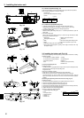
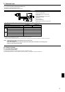
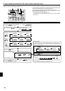
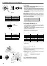
4.3. Indoor unit (Fig. 4-3)
Installing procedures
1. Slide the supplied pipe cover
over the gas tubing until it is pressed against the
sheet metal inside the unit.
2. Slide the provided pipe cover
over the liquid tubing until it is pressed against
the sheet metal inside the unit.
3. Tighten the pipe covers
and
at the both ends 3/4 in. (20 mm) with the sup-
plied bands
.
Gas tubing
Pipe cover
Liquid tubing
Press the pipe cover against the sheet metal.
Band
Refrigerant tubing heat insulating material
Pipe cover
4.4. For twin combination
Refer to the outdoor unit installation manual.
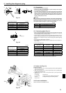
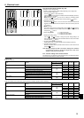
4.1. Precautions
For devices that use R410A refrigerant
• Use ester oil, ether oil or alkylbenzene oil (small amount) as the refrigera-
tion oil applied to the flared sections.
• Use C1220 copper phosphorus for copper and copper alloy seamless
pipes, to connect the refrigerant pipes. Use refrigerant pipes with the thick-
nesses specified in the table below. Make sure the insides of the pipes are
clean and do not contain any harmful contaminants such as sulfuric com-
pounds, oxidants, debris, or dust.
Warning:
When installing or moving the air conditioner, use only the specified refriger-
ant (R410A) to charge the refrigerant lines. Do not mix it with any other refrig-
erant and do not allow air to remain in the lines. Air enclosed in the lines can
cause pressure peaks resulting in a rupture and other hazards.
in. (mm)
A24, 30, 36, 42
Liquid pipe 3/8" (ø9.52) thickness 1/32" (0.8)
Gas pipe 5/8" (ø15.88) thickness 3/64" (1.0)
• Do not use pipes thinner than those specified above.
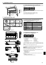
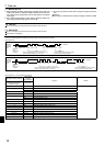
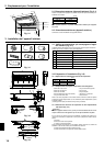
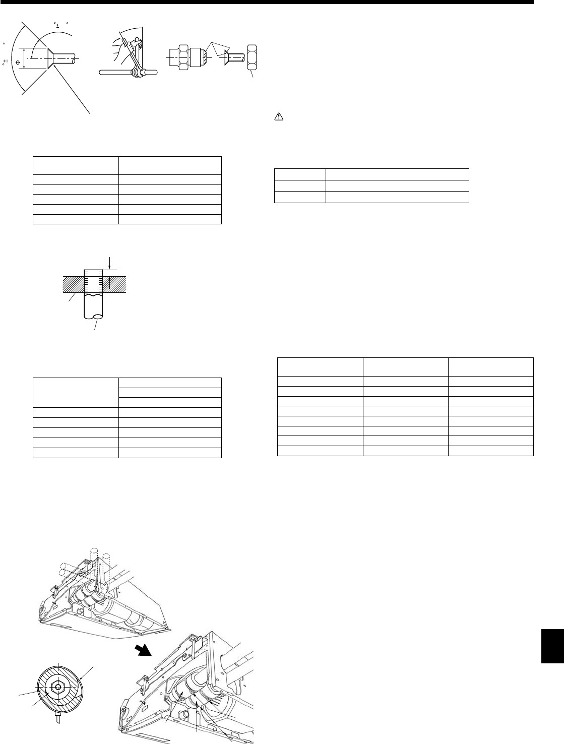
4.2. Connecting pipes (Fig. 4-1)
• When commercially available copper pipes are used, wrap liquid and gas pipes
with commercially available insulation materials (heat-resistant to 212 °F (100 °C)
or more, thickness of 1/2 in. (12 mm) or more).
• The indoor parts of the drain pipe should be wrapped with polyethylene foam in-
sulation materials (specific gravity of 0.03, thickness of 23/64 in. (9 mm) or more).
• Apply thin layer of refrigerant oil to pipe and joint seating surface before tightening
flare nut.
• Use 2 wrenches to tighten piping connections.
• Use refrigerant piping insulation provided to insulate indoor unit connections. In-
sulate carefully.
Flare nut tightening torque
Copper pipe O.D.
(mm, inch)
Flare nut O.D.
(mm, inch)
Tightening torque
(N-m, ft.lbs)
ø6.35, 1/4 17, 43/64 14-18, 10-13
ø6.35, 1/4 22, 7/8 34-42, 25-30
ø9.52, 3/8 22, 7/8 34-42, 25-30
ø12.7, 1/2 26, 1-3/64 49-61, 35-44
ø12.7, 1/2 29, 1-9/64 68-82, 49-59
ø15.88, 5/8 29, 1-9/64 68-82, 49-59
ø15.88, 5/8 36, 1-27/64 100-120, 71-86
ø19.05, 3/4 36, 1-27/64 100-120, 71-86
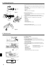
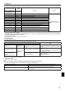
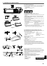
Apply refrigerating machine oil over the entire flare seat surface.
Use correct flare nuts meeting the pipe size of the outdoor unit.
Flare cutting dimensions in. (mm)
Copper pipe O.D.
Flare dimensions
øA dimensions
1/4” (ø6.35) 11/32-23/64 (8.7 - 9.1)
3/8" (ø9.52) 1/2-33/64 (12.8 - 13.2)
1/2" (ø12.7) 41/64-21/32 (16.2 - 16.6)
5/8" (ø15.88) 49/64-25/32 (19.3 - 19.7)
3/4" (ø19.05) 29/32-59/64 (22.9 - 23.3)
in. (mm)
Copper pipe O.D.
B
Flare tool for R410A
Clutch type
1/4” (ø6.35) 0-1/64 (0 - 0.5)
3/8" (ø9.52) 0-1/64 (0 - 0.5)
1/2" (ø12.7) 0-1/64 (0 - 0.5)
5/8" (ø15.88) 0-1/64 (0 - 0.5)
3/4" (ø19.05) 0-1/64 (0 - 0.5)
90 0.5
A
R1/64 to R1/32
45 2
Die
Copper pipe
B
Fig. 4-3
Fig. 4-1
Fig. 4-2