


3
3. Installing the indoor unit
2. Installation location
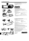
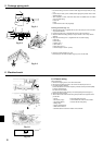
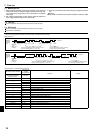
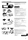
3.1. Check the indoor unit accessories (Fig. 3-1)
The indoor unit should be supplied with the following accessories
(contained in the inside of the intake grille).
Accessory name Q’ty
Washer 4 pcs
Pipe cover 1 pc Large size (For gas tubing)
Pipe cover 1 pc Small size (For liquid tubing)
Band 4 pcs
Joint socket 1 pc Marked with “UNIT”
Socket cover 1 pc
Drain tubing cover 1 pc
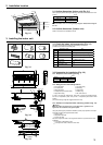
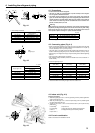
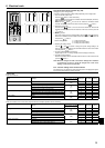
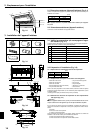
2.1. Outline dimensions (Indoor unit) (Fig. 2-1)
Select a proper position allowing the following clearances for installation and main-
tenance.
(inch)
Models W
A24, 30 50-3/8
A36, 42 63
Warning:
Mount the indoor unit on a ceiling strong enough to withstand the weight of
the unit.
2.2. Outline dimensions (Outdoor unit)
Refer to the outdoor unit installation manual.
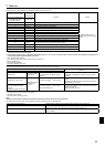
3.2. Preparation for installation (Fig. 3-2)
3.2.1. Suspension bolt installing spacing
(inch)
Models A B
A24,30 48-11/16 50-3/8
A36,42 61-5/16 63
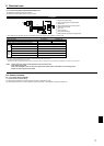
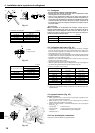
3.2.2. Refrigerant and drain tubing location
Front side outlet
Left drain tubing
Left side outlet
Gas tubing
Right side outlet
Liquid tubing
Independent piece (Removable)
Rubber plug
Right drain tubing
with Joint socket
In case of the rear pipe arrangement, make sure to remove the shaded portions
from the
independent piece. Then put the
independent piece back in initial
position.
(The heat exchanger might be clogged because of dust)
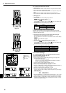
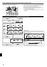
3.2.3. Selection of suspension bolts and tubing positions (Fig. 3-3)
Caution:
Install the indoor unit at least 8 ft. (2.4 m) above floor or grade level. For
appliances not accessible to the general public.
Using the pattern paper provided for installation, select proper positions for suspen-
sion bolts and tubing and prepare relative holes.
Pattern paper
Suspension bolt hole
Indoor unit width
Secure the suspension bolts or use angle stock braces or square timbers for bolt
installation.
Use inserts of 220-230 lbs. each.
Use suspension bolts of W 3/8 or M10 in size.
W
Min. 10-5/8
Min. 11-13/16
Max. 9-13/16
9-5/16
Min. 19-11/16
26-3/4
A
9-5/16
B
1/16
2-15/16
3-1/812-5/8
26-3/4
1/16
7-1/21-13/16
1/4
9-3/16
9-11/16
7-1/16
7-7/8
9-3/16
9-11/16
3-3/8
1/16
3-3/8
5-7/16
4-15/16
7-1/2
1-13/16
4-15/16
6-5/167-1/2
2-3/4
3-1/8 Ø2-9/16 Ø3-15/16
Fig. 2-1
Fig. 3-1
70+6
Fig. 3-2
Fig. 3-3