8
7-3. Connecting the Signal Lines
• Separately procure items such as terminal blocks and cables locally.
• The maximum wire length is 100 m. However, since the use of long wires makes the device susceptible to
noise, using wires shorter than 10 m is recommended.
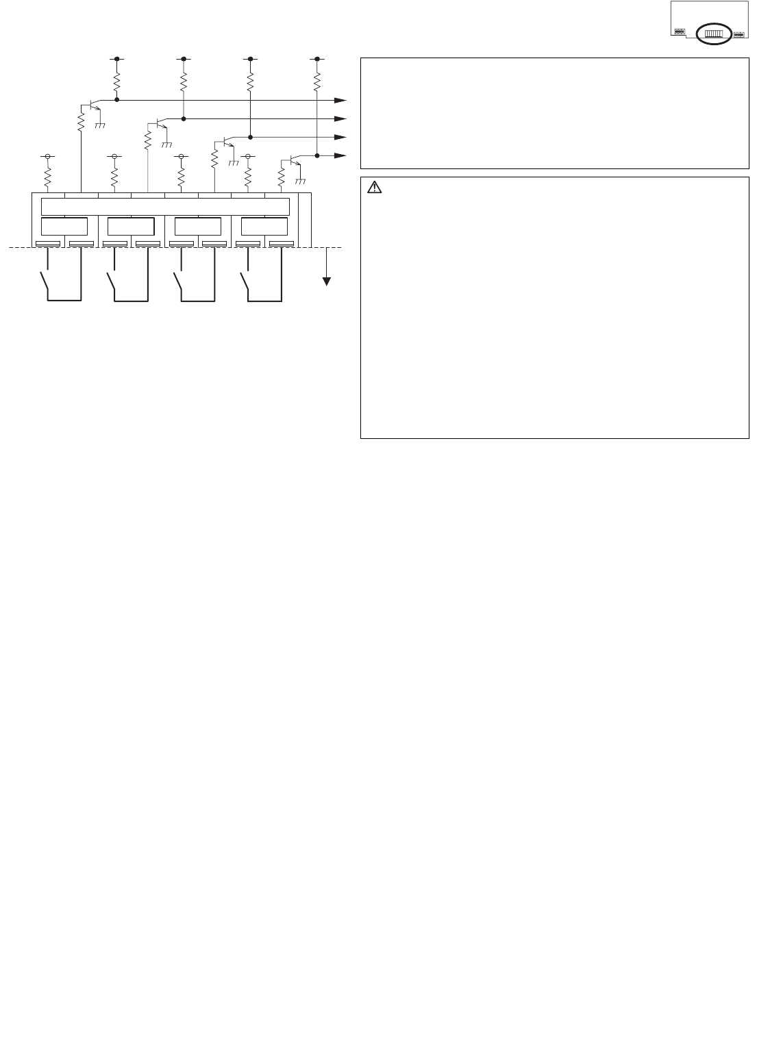
(1) Pulse input (non-voltage a contact)
* To use these, various settings need to be configured. Refer to "8 Initial Setting Procedure".
Ch1 Ch3
C
N 1
0
/
11
/
1
9
/
2
0
Ch2 Ch4
++++
Note:
• The pulse weight can be added to each of the inputs of
channels 1 to 4.
For details, refer to "9 Switch List".
• This device does not support level meters.
To use a level meter, incorporate a Converter circuit
externally and convert to pulse input.
Caution:
• The polarity of the input terminals is important, so be sure to
match the polarity when using contacts that have polarity.
• Select a contact with a minimum applicable load of 1 mA or
less.
• Supply 24 VDC 1 mA from the positive terminal to the
contacts of the meters.
• The pulse unit of the watt-hour meter being used should be
1 kWh/pulse or less. Note that the apportioning error will
increase if a watt-hour meter with large pulse unit is used.
• Strip 12±1 mm (15/32 ±1/32 in) of the wire coating and insert
firmly into the terminal.
• Make sure that the copper wiring is not short-circuiting the
plates (cover, lower case) or neighboring wires.
• Perform wiring so that the terminal block is not strained.
If strained, use a wire guide or junction terminal to alleviate
the stress on the terminal block.
Watthour
meter
Water
meter
Gas
meter
Calorimeter
Line
Onsite
Example:
24 VDC


