


6
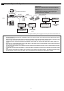
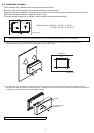
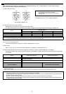
(3) Refer to "7 Wiring Method" and connect the wires for the power line, M-NET transmission line, and input/output signal lines.
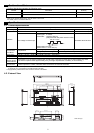
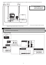
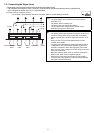
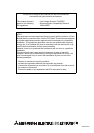
7-1. Names of Parts
PAC
-
SC50KUA
M-NET
NFG L-V+V
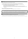
Diagram Image (Installed within a Control Panel)
* The wiring in the diagram has been simplified.
M-NET Pulse Input Power line
PI controller
Caution: Perform wiring so that the terminal
block is not strained.
If strained, use a wire guide or
junction terminal to alleviate the
stress on the terminal block.
24 VDC
Power
source
Junction
terminal
block
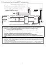
7 Wiring Method
Note: Connecting an Uninterruptible power supply (UPS) to the 24 VDC power supply is recommended in order to prevent the loss of
pulse data in the event of a power failure.
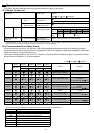
CN16
SW03
SW01
SW08
SW02
SW09
SW06
SW07
LED
CN17
LED17
A / B / S
CN10 / 11 /19 / 20
V+ / V- / FG
11/ 12/ 13/ 14/ 15/ 16
M-NET
Power on
24 VDC Power Supply
M-NET
Address
Status LEDs
M-NET
Function Settings
Pulse Input
10s 1s
(CPU power on)