


8
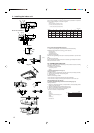
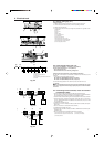
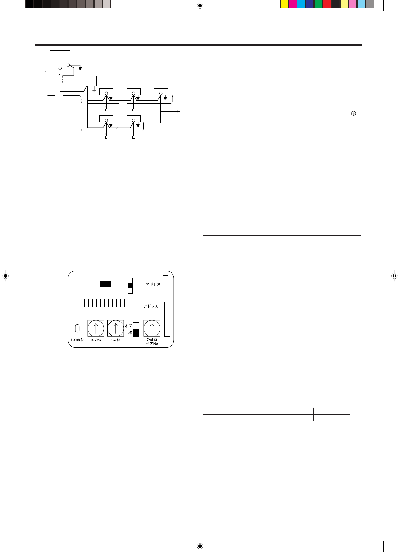
6.4. Setting addresses (Fig. 6-6)
(Be sure to operate with the main power turned OFF.)
• There are two types of rotary switch setting available: setting addresses 1 to 9 and
over 10, and setting branch numbers.
1 How to set addresses
Example: If Address is “3”, remain SW12 (for over 10) at “0”, and match SW11(for
1 to 9) with “3”.
2 How to set branch numbers (Series R2 only)
Match the indoor unit’s refrigerant pipe with the-xC controller’s end connection
number. Remain SW14 other than R2 at “0”.
• The rotary switches are all set to “0” when shipped from the factory. These switches
can be used to set unit addresses and branch numbers at will.
• The determination of indoor unit addresses varies with the system at site. Set them
referring to technical data.
Note:
Please set the switch SW5 according to the power supply voltage.
• Set SW5 to 230 V side when the power supply is 230 volts.
• When the power supply is 208 volts, set SW5 to 208 V side.
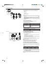
6.5. Switch setting for different ceiling heights
With this unit, the air flow rate and fan speed can be adjusted by setting the SWA
(slide switch). Select a suitable setting from the table below according to the installa-
tion location.
* Make sure the SWA switch is set, otherwise problems such as no wind blowing will
occur.
Ceiling Height 11.5 ft. (3.5 m) 9.2 ft. (2.8 m) 7.5 ft. (2.3 m)
SWA 3 (high ceiling) 2 (standard) 1 (low ceiling)
SWA: Factory setting: 2 (Standard)
6.6. Sensing room temperature with the built-in sensor
in a remote controller
If you want to sense room temperature with the built-in sensor in a remote controller,
set SW1-1 on the control board to “ON”. The setting of SW1-7 and SW1-8 as neces-
sary also makes it possible to adjust the air flow at a time when the heating thermom-
eter is OFF.
Fig. 6-6
Address board
6. Electrical work
G
I
JJJ
KK
KK
JJ
L
K
H
*1
*3
L1
L2
L4
r
L3
*2
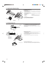
Remarks
Fig. 6-5
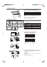
Constraints on transmission cable
Longest wiring length (L1+L2+L4 or L1+L3 or L2+L3+L4): less than 656 ft (200 m)
Length between indoor unit and remote controller (R): within 33 ft (10 m)
G Outdoor unit
H Earth
I BC controller
J Indoor unit
K M-NET Remote controller
L Non-polarized 2-wire
Note:
*1 Put the transmission cable earth via the outdoor unit’s earth terminal
to
the ground.
*2 If the remote controller cable exceeds 33 ft (10 m), use a 1.25 mm
2
(AWG16)
diameter cable over the exceeded portion, and add that exceeded portion
to within 656 ft (200 m).
*3 The BC controller is required only for simultaneous cooling and heating
series R2.
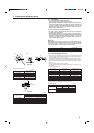
Types of control cables (Fig. 6-5)
1. Wiring transmission cables: Shielding wire CVVS or CPEVS
• Cable diameter: More than 1.25 mm
2
(AWG16)
2. M-NET Remote control cables
Kind of remote control cable 2-core cable (unshielded)
Cable diameter More than 0.5 (AWG20) to 0.75 mm
2
(AWG18)
When 10 m is exceeded, use cable with the
same specifications as transmission line wiring
(shielding portion is more than 1.25 mm
2
(AWG16))
3. MA Remote control cables
Kind of remote control cable 2-core cable (unshielded)
Cable diameter 0.3 mm
2
(AWG22) to 1.25 mm
2
(AWG16)
SW14
0
SW11
0
SW12
0
12345678910
ON
OFF
SW1
SW5
220V
(208V)
240V
(230V)
SWC
CN82
CN43
3
2
SWA
1