


4
Fig. 3-8
Fig. 3-5
Fig. 3-6
Fig. 3-7
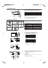
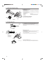
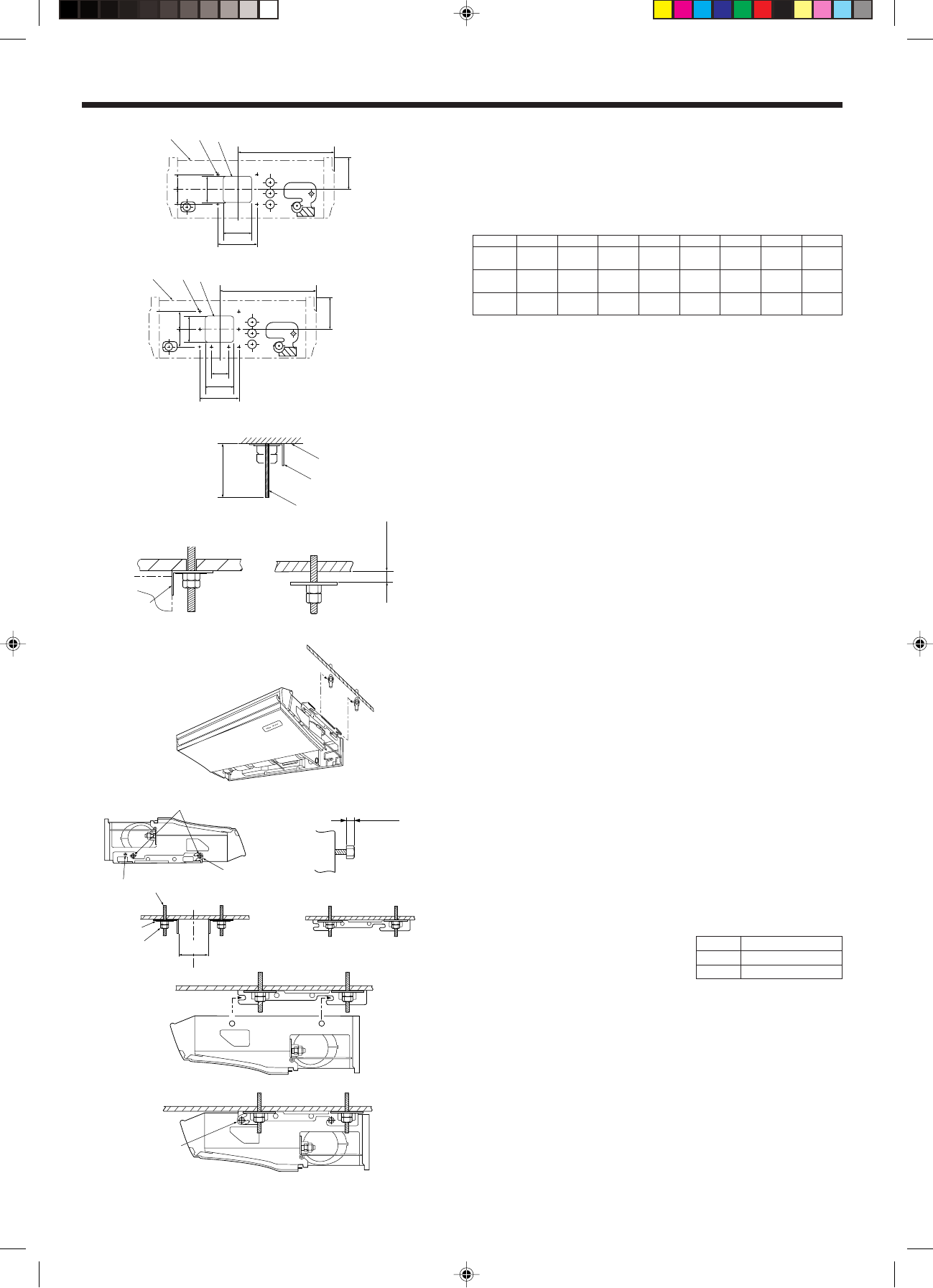
3.2.5. Indoor unit preparation (Fig. 3-5)
1. Install the suspending bolts. (Procure the W3/8 or M10 bolts locally.)
Predetermine the length from the ceiling (1 within 100 mm).
A Ceiling surface
B Suspending bolt
C Suspending bracket
2. Remove the intake grille.
Slide the intake grille holding knobs (at two locations) backward to open the intake
grille.
3. Remove the side panel.
Remove the side panel holding screws (one in each side, right and left) then slide the
side panel forward for removal.
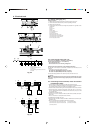
3.3. Installing the indoor unit
Use a proper suspending method depending on the presence or absence of ceiling
materials as follows. (Fig. 3-6)
In the absence of ceiling materials
a Suspending bracket
b Unit
1) Directly suspending the unit (Fig. 3-7)
Installing procedures
1. Install the washer 1 (supplied with the unit) and the nut (to be locally procured).
2. Set (hook) the unit through the suspending bolts.
3. Tighten the nuts.
Check the unit installing condition.
• Check that the unit is horizontal between the right and left sides.
• Check that the unit slopes continuously downward from the front to the rear.
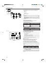
When embedding pipes, into the wall
2) Installing the suspending bracket first onto the ceiling (Fig. 3-8)
Installing procedures
1. Remove the suspending brackets, U-shaped washers, and suspending bracket
holding screws from the unit.
2. Adjust the suspending bracket holding bolts on the unit.
3. Attach the suspending brackets to the suspending bolts.
4. Set (hook) the unit to the suspending brackets.
∗ Be sure to install the U-shaped washers.
A Bolt
B Unit
C Washer
D Suspending bracket holding screw
E Bolt
F Washer 1
G Double nuts
B
A
C
1
(inch)
a
b
(inch)
H P15 35-7/16 - 35-41/64
P24, P30
47-1/2 - 47-23/32
P36 59-39/54 - 59-13/16
C
D
A
E
F
G
H
C
25/64-25/32
1/4-15/32
B
3. Installing the indoor unit
A
F
G
B
ED
C
A
C
B
F
H
A
G
B
ED
C
A
C
B
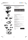
■ PCFY-P15, P24NGMU-E
■ PCFY-P30, P36NGMU-E
Fig. 3-4
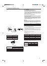
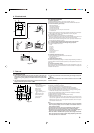
3.2.4. Fresh air intake hole (Fig. 3-4)
At the time of installation, use the duct holes (knock out) located at the positions
shown in following diagram, as and when reguired.
A Indoor unit
B Fresh air intake hole (knock out hole)
C 4-ø1/8" (ø2.8) burring hole (P15, P24)
8-ø1/8" (ø2.8) burring hole (P30, P36)
inch (mm)
Models A B C D E F G H
P15
12-23/32 3-3/16 2-7/16 1-25/32 1-21/32 1-3/4 2-29/32
–
(323.1) (80.9) (62) (45) (42) (44.6) (73.6)
P24
13-29/32 3-11/32 2-1/8 1-5/8 1-1/2 3-31/32 5-9/32
–
(353.6) (84.7) (54) (41) (38) (100.5) (134.5)
P30,P36
16-15/16 5-7/32 5-29/32 3-21/32 3-21/32 7-7/8 9-9/32 3-15/16
(430) (132.3) (150) (93) (93) (200) (236) (100)