


3
2. Installation location
3. Installing the indoor unit
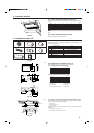
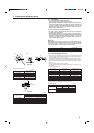
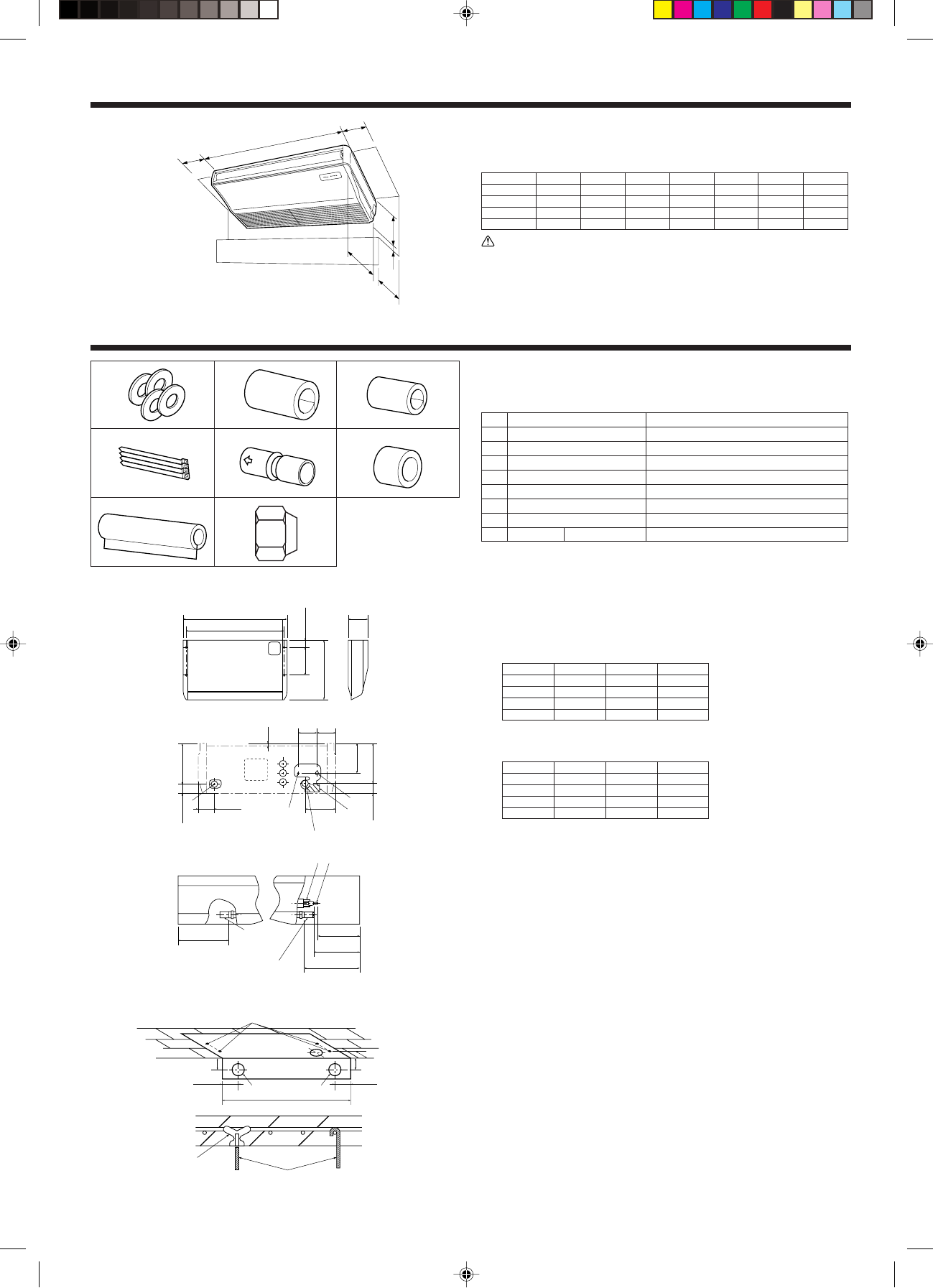
3.1. Check the indoor unit accessories (Fig. 3-1)
The indoor unit should be supplied with the following accessories (contained in the
inside of the intake grille).
Accessory name Q’ty
1 Washer 4 pcs
2 Pipe cover 1 pc Large size (For gas tubing)
3 Pipe cover 1 pc Small size (For liquid tubing)
4 Band 4 pcs
5 Joint socket 1 pc Marked with “UNIT”
6 Socket cover 1 pc
7 Drain tubing cover 1 pc
8 Flare nut P36 1 <3/4" (ø19.05)>
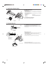
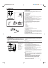
Fig. 2-1
2.1. Outline dimensions (Indoor unit) (Fig. 2-1)
Select a proper position allowing the following clearances for installation and mainte-
nance.
(inch)
Models W D H ABCE
P15 39-5/8 26-7/32 8-9/32
Min.10-5/8
Min.11-13/16 Min.19-11/16 Max. 9-13/16
P24 51-9/16 26-7/32 8-9/32
Min.10-5/8
Min.11-13/16 Min.19-11/16 Max. 9-13/16
P30 51-9/16 26-7/32 10-5/8
Min.10-5/8
Min.11-13/16 Min.19-11/16 Max. 9-13/16
P36 63-3/4 26-7/32 10-5/8
Min.10-5/8
Min.11-13/16 Min.19-11/16 Max. 9-13/16
Warning:
Mount the indoor unit on a ceiling strong enough to withstand the weight of the
unit.
2.2. Outline dimensions (Outdoor unit)
Refer to the outdoor unit installation manual.
1
2
3
4
5
6
7
Fig. 3-1
Fig. 3-2
Fig. 3-3
E
D
H
C
W
A
B
UNIT
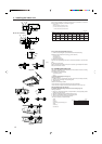
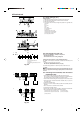
3.2. Preparation for installation (Fig. 3-2)
Must be installed at least 8 ft. (2.4 m) above floor or grade level.
3.2.1. Suspension bolt installing spacing
(inch)
Models A B C
P15 36-23/32 39-5/8 8-9/32
P24 48-13/16 51-9/16 8-9/32
P30 48-13/16 51-9/16 10-5/8
P36 60-29/32 63-3/4 10-5/8
3.2.2. Refrigerant and drain tubing location
(inch)
Models D E F
P15 5-5/32 6-7/8 7-1/16
P24 5-5/32 6-7/8 7-1/16
P30 7-9/16 9-9/32 7-2/32
P36 7-1/2 9-9/32 7-2/32
A Front side outlet E Right drain tubing
B Left side outlet F Left drain tubing
C Right side outlet G Gas tubing
D Independent piece (Removable) H Liquid tubing
A
B
(inch)
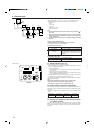
3.2.3. Selection of suspension bolts and tubing positions (Fig. 3-3)
Using the pattern paper provided for installation, select proper positions for suspen-
sion bolts and tubing and prepare relative holes.
A Pattern paper
B Suspension bolt hole
C Indoor unit width
Secure the suspension bolts or use angle stock braces or square timbers for bolt
installation.
A Use inserts of 220-230 lbs. each.
B Use suspension bolts of W3/8 or M10 in size
8
A
C
B
26-3/4
12-19/32
3-19/128
5-7/16
3-3/83-5/8
7/16
D
E
F1-11/16
A
F
H D
G
E
2-61/64
1-13/16
A
C
B
4-59/64
5-121/128(8-5/16)6-11/16(9-7/128)
2-3/4
3-19/128 Ø2-1/2 Ø3-15/16
(inch)
C
7-3/16
H
G
E
GH
F
B
8-7/8
7-13/16
9-5/8