


7
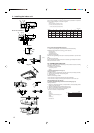
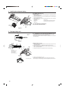
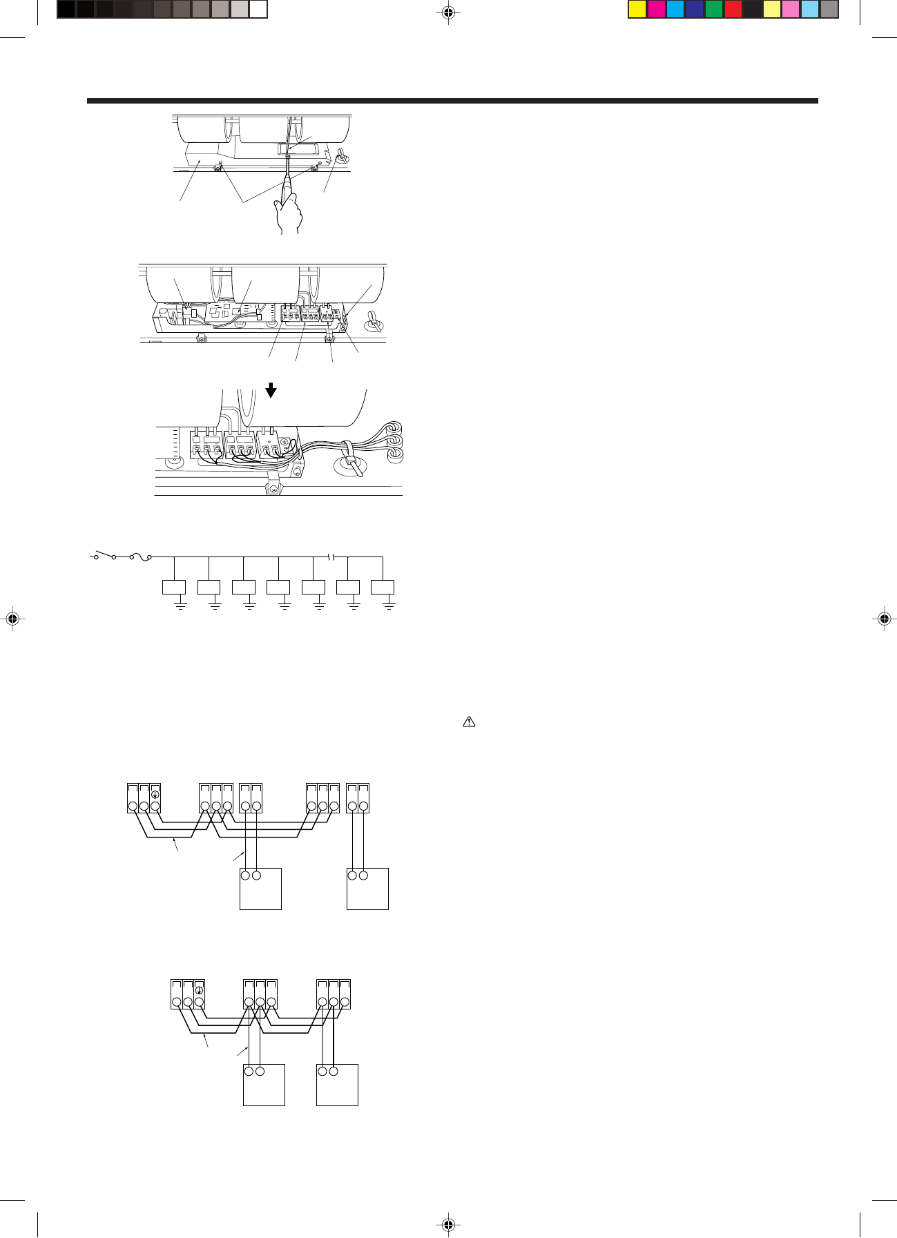
6.2. Power supply wiring (Fig. 6-2)
Power cable size (diameter) : more than 1.6 mm (AWG14)
Ground cable size (diameter) : 1.6 mm (AWG14)
* Use copper supply wires.
* Use the electric wires over the rating voltage 300 V.
[Selecting non-fuse breaker (NF) or earth leakage breaker (NV)]
To select NF or NV instead of a combination of Class B fuse with switch, use the
following:
• In the case of Class B fuse rated 15 A or 20 A,
NF model name (MITSUBISHI): NF30-CS (15 A) (20 A)
NV model name (MITSUBISHI): NV30-CA (15 A) (20 A)
Use an earth leakage breaker with a sensitivity of less than 30 mA 0.1 sec.
Caution:
Do not use anything other than the correct capacity breaker and fuse. Using
fuse, wire or copper wire with too large capacity may cause a risk of malfunc-
tion or fire.
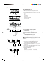
6.3. Connecting remote controller, indoor and outdoor
transmission cables
• Connect indoor unit TB5 and outdoor unit TB3. (Non-polarized 2-wire)
The “S” on indoor unit TB5 is a shielding wire connection. For specifications about
the connecting cables, refer to the outdoor unit installation manual.
• Install a remote controller following the manual supplied with the remote controller.
• Connect the remote controller’s transmission cable within 33 ft (10 m) using a
0.75 mm
2
(AWG18) core cable. If the distance is more than 33 ft (10 m), use a 1.25
mm
2
junction cable.
1 MA Remote controller (Fig. 6-3)
• Connect the “1” and “2” on indoor unit TB15 to a MA remote controller. (Non-polar-
ized 2-wire)
• DC 9 to 13 V between 1 and 2 (MA remote controller)
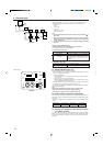
2 M-NET Remote controller (Fig. 6-4)
• Connect the “M1” and “M2” on indoor unit TB5 to a M-NET remote controller. (Non-
polarized 2-wire)
• DC 24 to 30 V between M1 and M2 (M-NET remote controller)
A Terminal block for indoor transmission cable D Transmission cables
B Terminal block for outdoor transmission cable E Remote control cables
C Remote controller
AB D
E
CCCCCCC
1
2
AA
C
TB5 TB15 TB5 TB15
SM1M2 SM1M2
B
TB3
M1M2 21
C
21
D
E
AA
C
TB5 TB5
SM1M2 SM1M2
C
B
TB3
M1M2
D
E
A Switch 15 A
B Overcurrent protection 15 A
C Indoor unit
D Total operating current be less than 15 A
E Ground
Fig. 6-2
Fig. 6-3
Fig. 6-4
M1
L2
GR
1
M2
S
2
L1
D
C
B
A
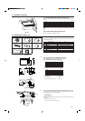
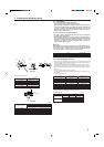
6.1. Electric wiring (Fig. 6-1)
Wiring procedures
1. Remove the (two) tapping screws then remove the electric part cover.
2. Connect the electric wires securely to the corresponding terminals.
3. Replace the removed parts.
4. Tie the electric wires with the local wiring clamp located in the right side of the
junction box.
A Cover
B Set screws
C Beam
D Wiring clamp
E Power supply board
F Control board
G Wire service entrance
H Terminal block for power supply
I Terminal block for transmission cable
J Terminal block for remote controller
K Grounding cable connector
Fig. 6-1
6. Electrical work
L1
L2
GR
M1
1
M2
S
2
G
K
F
J
I
H
E