


6
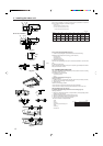
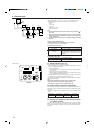
Installing procedures (Fig. 5-2)
1. Attach the joint socket 5 supplied with the unit to the drain port on the unit with a
vinyl chloride adhesive.
2. Fasten the socket cover 6 supplied with the unit to the joint socket 5.
3. Attach the field drain tubing (VP20/O.D. ø26 PVC TUBE) to the joint socket 5
with a vinyl chloride adhesive.
4. Wrap the drain tubing cover 7 supplied with the unit. (Seam taping)
5. Check for correct drainage. (Fig. 5-3)
∗ Fill the drain pan with water of about 1 L from the tubing sensor access port.
∗ After checking for correct drainage, replace the tubing sensor access port cover.
3.B
1.D
2.C
4.E
B
C
D
A
E
F
Fig. 5-2
Fig. 5-3
A Drain pan
B Drain tubing (VP20)
C Socket cover 6
D Joint socket 5
E Drain tubing cover 7
F Drain tubing sensor
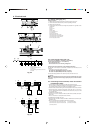
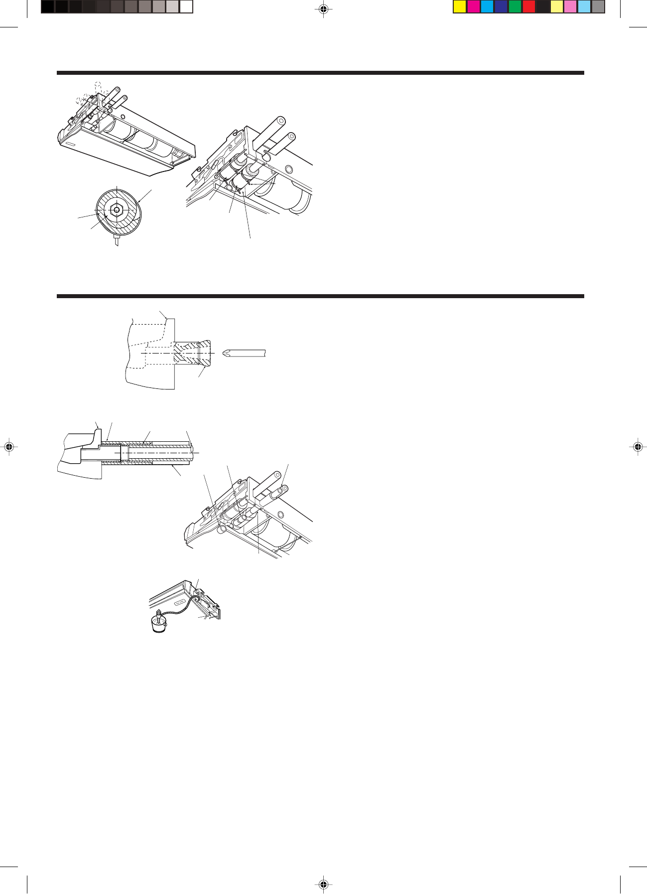
5. Drainage piping work
B
A
5.1. Preparation for left side tubing installation (Fig. 5-1)
• For left side tubing, be sure to insert the rubber plug into the right drain port.
• Install the drain tubing as it slopes continuously downward.
• After completion of work, check that correct drain is available from the outflow port
of the drain tubing.
A Drain pan
B Plug
Fig. 5-1
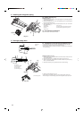
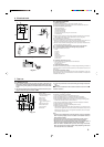
4. Installing the refrigerant piping
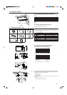
4.3. Indoor unit (Fig. 4-3)
Installing procedures
1. Slide the supplied pipe cover 2 over the gas tubing until it is pressed against the
sheet metal inside the unit.
2. Slide the provided pipe cover 3 over the liquid tubing until it is pressed against
the sheet metal inside the unit.
3. Tighten the pipe covers 2 and 3 at the both ends 5/8 - 3/4 in. (15 - 20 mm) with
the supplied bands 4.
A Gas tubing E Pipe cover 3
B Liquid tubing F Press the pipe cover against the sheet metal.
C Band 4 G Refrigerant tubing heat insulating material
D Pipe cover 2
4.4. For twin/triple combination
Refer to the outdoor unit installation manual.
G
C
DE
A
B
D
E
F
C
Fig. 4-3