


39
OPERATING PROCEDURE
PHOTOS
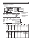
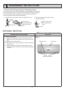
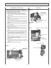
6. Removing the horizontal vane motor
(1) Remove the nozzle assembly. (Refer to 4.)
(2) Remove the screws of the horizontal vane motor unit, and
pull out the horizontal vane motor unit.
(3) Remove the screws of the horizontal vane motor unit cover.
(4) Remove the horizontal vane motor from the horizontal vane
motor unit.
(5) Disconnect the connector from the horizontal vane motor.
7. Removing the indoor fan motor and the line flow fan
(1) Remove the panel (refer to 1.) and the corner box.
(2) Remove the sensor holder, the power monitor receiver P.C.
board holder, the electrical box (refer to 3.) and the nozzle
assembly (Refer to 4.).
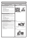
(4) Remove the screws fixing the motor bed. (See Photo 9)
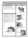
(5) Loosen the screw fixing the line flow fan. (See Photo 10)
(6) Remove the motor bed together with fan motor and motor
band.
(7) Release the hooks of the motor band. Remove the motor
band. Pull out the indoor fan motor.
(8) Remove the indoor coil thermistor from the heat exchanger.
( ) Install the indoor coil thermistor (RT12) in its former posi-
tion when assembling it. (See to Photo 12)
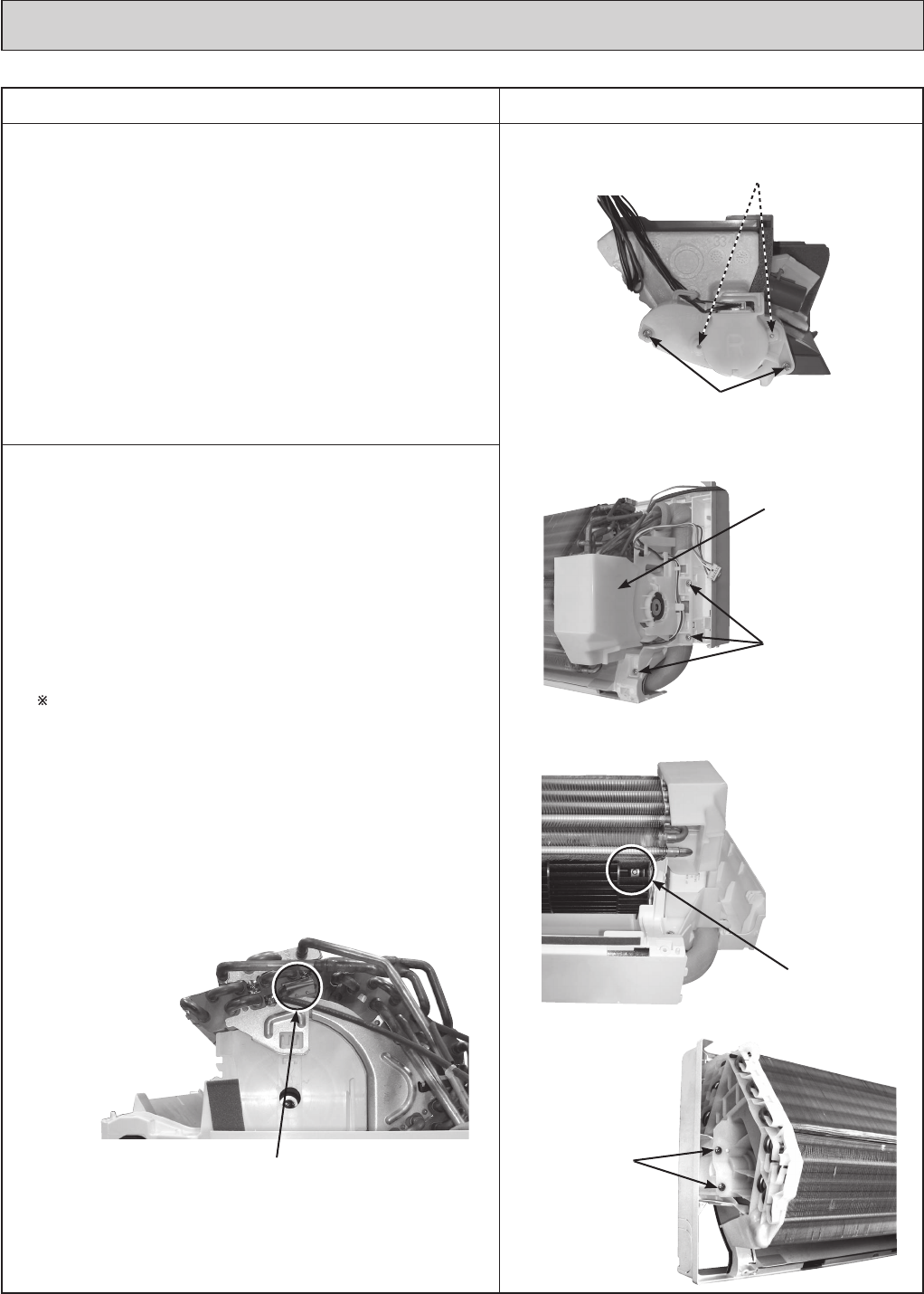
(9) Remove the screws fixing the left side of the heat exchang-
er. (See Photo 11)
(10)
Lift the heat exchanger, and pull out the line flow fan to the
lower-left.
Photo 8
Screws of the horizontal
vane motor unit cover
Screws of the horizontal vane motor unit
Photo 12
Indoor coil thermistor (RT12)
Photo 9
Photo 11
Photo 10
Motor band
Screws of the
motor bed
Screw of the line
flow fan
Screws of the
left side of the
heat exchanger