


34
MSZ-FD09NA MSZ-FD12NA
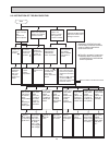
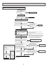
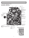
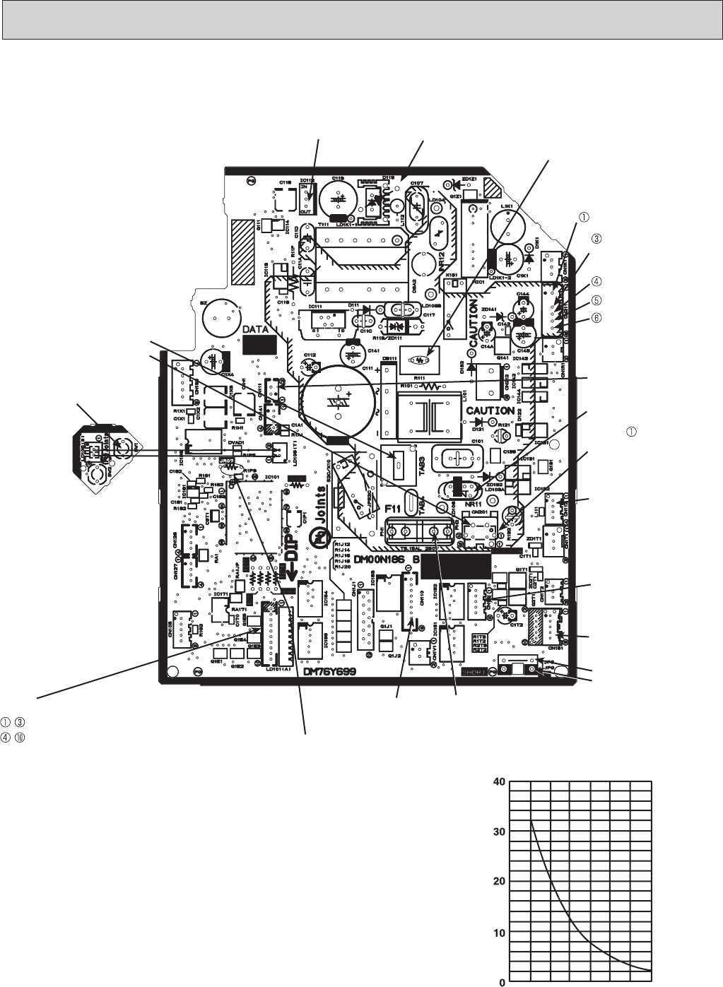
Indoor electronic control P.C. board
9-7. TEST POINT DIAGRAM AND VOLTAGE
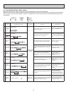
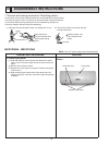
Room temperature thermistor (RT11)
Indoor coil thermistor (RT12, RT13)
Temperature (°F)
Resistance (kΩ)
32
50 68 86 104122 140
Release of Auto restart
function
Solder the Jumper wire
JR07
(Refer to 7-3.)
12 VDC
Varistor (NR11)
5 VDC
Room temperature
thermistor RT11
(CN111)
Indoor coil thermistor
RT12, RT13 (CN112)
Timer short mode
point JPG, JPS
(Refer to 7-1.)
}
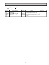
SW P.C. Board
i-see Sensor
(CN110)
Fuse
(F11)
Vertical vanes (CN151)
CN201
(Used for check of con-
ducting of thermal fuse)
(+)0 or 15 VDC
(+)3 - 6 VDC
15
VDC
(-) Fiducial terminal of
cathode side on measur-
ing high-voltage DC
294/325 VDC
Cement resistor
(R111)
Indoor fan motor
(CN211)
Emergency
operation
switch (SW1)
208/230 VAC
Power supply input
{
(LD101)
- : Connect to the monitor P.C.board
- : Connect to the power monitor receiver
P.C.board
Horizontal vane (CN1U1)