


2828
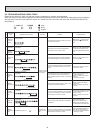
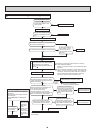
9-5. TROUBLE CRITERION OF MAIN PARTS
MSZ-FD09NA MSZ-FD12NA
Part name Check method and criterion Figure
Room temperature therm-
istor (RT11)
Indoor coil thermistor
(RT12, RT13)
Measure the resistance with a tester.
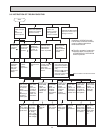
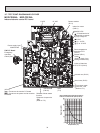
Refer to 9-7. "Test point diagram and voltage", "Indoor electronic control P.C.
board", the chart of thermistor.
Indoor fan motor (MF) Check 9-6.
.
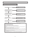
Horizontal vane motor
(MV1)
Vertical vane motor
(MV2)
i-see Sensor motor
(MT)
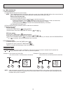
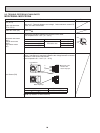
Measure the resistance between the terminals with a tester.
(Part temperature 50 ~ 86°F (10 ~ 30°C))
Color of the lead wire Normal
Horizontal vane motor (MV1)
BRN-other one
313 ~ 375 Ω
Vertical vane motor (MV2) 268 ~ 322 Ω
i-see Sensor motor (MT) 223 ~ 268 Ω
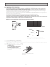
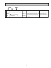
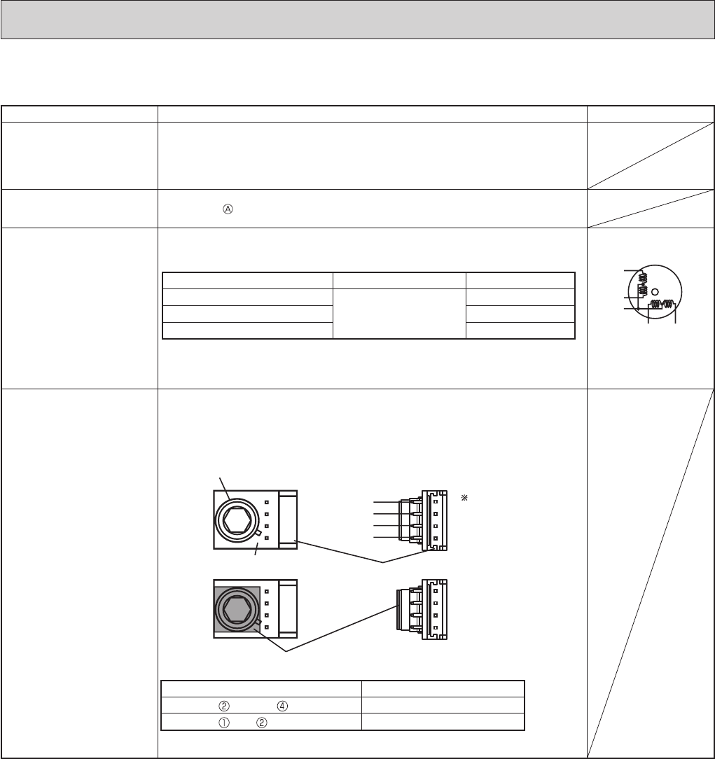
i-see Sensor (RR)
Cover the i-see Sensor with black vinyl tape. Then, turn ON the power
supply. (i-see Sensor is energized.) Measure the voltage between connector
terminals of i-see Sensor with a tester.
(Part temperature 50 ~ 104°F (10 ~ 40°C))
i-see Sensor connector terminals Normal range
(GND) - (+) 1.874 ~ 3.387 VDC
(+) - (GND) 1.010 ~ 1.420 VDC
NOTE: Pay attention to static electricity.
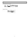
RED
YLW
BRN
ORN
GRN
ROTOR
Cover the i-see
Sensor with
black vinyl tape.
i-see Sensor
i-see Sensor P.C. board
Black vinyl tape
connector
4
3
2(GND)
1