


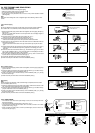
3-3. PIPE CONNECTION
)DVWHQÀDUHQXWZLWKDWRUTXHZUHQFKDVVSHFL¿HGLQWKHWDEOHUHIHUWR
:KHQIDVWHQHGWRRWLJKWÀDUHQXWPD\HYHQWXDOO\EUHDNDQGFDXVHUHIULJHUDQWOHDNDJH
Indoor unit connection
Connect both liquid and gas pipings to indoor unit.
• Apply a thin coat of refrigerant oil (J) on the seat surface of pipe.
7RFRQQHFW¿UVWDOLJQWKHFHQWHUWKHQWLJKWHQWKH¿UVWWRWXUQVRIÀDUHQXW
• Use tightening torque table above as a guideline for indoor unit side joints, and tighten
XVLQJWZRZUHQFKHV([FHVVLYHWLJKWHQLQJGDPDJHVWKHÀDUHVHFWLRQ
Outdoor unit connection
Connect pipes to stop valve pipe joint of the outdoor unit following the same procedure
detailed in Indoor unit connection.
• For tightening, use a torque wrench or spanner.
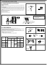
3-4. INSULATION AND TAPING
1) Cover piping joints with pipe cover.
2) For outdoor unit side, insulate the piping, including valves.
3) Apply piping tape (G) starting from the connection on the outdoor unit.
• When piping has to be installed through a ceiling, closet or where the temperature
DQGKXPLGLW\DUHKLJKXVHDGGLWLRQDO¿HOGVXSSOLHGLQVXODWLRQWRSUHYHQWFRQGHQVD
-
tion.
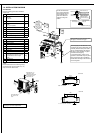
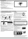
4-1. PURGING PROCEDURES AND LEAK TEST
1)
Remove service port cap of stop valve on the side of the outdoor unit gas pipe.
2) Connect gauge manifold valve and vacuum pump to service port of stop valve on the
gas pipe side of the outdoor unit.
4-5. EXPLANATION TO THE USER
• Using the OPERATING INSTRUCTIONS, explain to the user howto use the air condition-
HUWKHUHPRWHFRQWUROOHUUHPRYLQJWKHDLU¿OWHUVSODFLQJRUUHPRYLQJWKHUHPRWHFRQWUROOHU
from the remote controller holder, cleaning methods, precautions for operation, etc.)
• Recommend that the user read the OPERATING INSTRUCTIONS carefully.
Stop valve for
GAS
Stop valve cap
(Torque 19.6 to
29.4 N•m, 200
WRNJIƒFP
Vacuum pump (or the vacuum
pump with the function to
SUHYHQWWKHEDFNÀRZ
Gauge manifold valve
(for R410A)
Compound pressure gauge
(for R410A)
–0.101 MPa
(–30 in.Hg
[–760 mHg])
Handle
Low
Handle High
Adapter for pre
-
venting the back
ÀRZ
Charge hose
(for R410A)
*Close
*Open
Hexagonal wrench
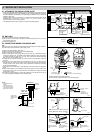
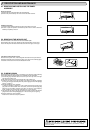
Precautions when using the control valve
When attaching the control valve
to the service port, valve core may
deform or loosen if excess pressure
is applied. This may cause gas leak.
Service port
Charge hose
Body
Close
Open
Control valve
A
When attaching the control valve to
the service port, make sure that the
valve core is in closed position, and
then tighten part A. Do not tighten
part Aor turn the body when valve
core is in open position.
Service port cap
(Torque 13.7 to
17.7 N•m, 140 to
180 kgf
•cm)
*4 to 5 turns
3) Run the vacuum pump 15 minutes or more.
4) Check the vacuum with the gauge manifold valve, then close it and shut off the vacuum
pump.
5) Leave as it is for one or two minutes. Make sure pointer gauge manifold valve remains
LQWKHVDPHSRVLWLRQ&RQ¿UPWKDWSUHVVXUHJDXJHVKRZV±03D>*DXJH@±
in.Hg [–760 mmHg]).
6) Quickly remove gauge manifold valve from service port of stop valve.
7) After refrigerant pipes are connected and evacuated, fully open all stop valves on both
sides of gas pipe and liquid pipe. Operating the unit without fully opening the valves
lowers the performance and causes problems.
8) Refer to 1-3. SPECIFICATIONS, and charge the prescribed amount of refrigerant if
needed. Be sure to charge slowly with liquid refrigerant. Otherwise, composition of the
refrigerant in the system may be changed and affect performance of the air conditioner.
9) Tighten cap of service port.
10) Conduct a leak test
Stop valve
for LIQUID
4. PURGING PROCEDURES, LEAK TEST, AND TEST RUN
Pressure gauge
(for R410A)
4-2. TEST RUN
1) Insert power supply plug into the power outlet and/or turn
on the breaker.
2) Press the E.O. SW once. Test run will be performed for
30 minutes. If the power lamp blinks every 0.5 seconds,
inspect the indoor/outdoor unit connecting wire (A). After
the test run, emergency COOL mode (75ºF [24ºC] COOL)
will start.
3) To stop operation, press the E.O. SW several times until
all LED lamps turn off. Refer to operating instructions for
details.
Checking the remote (infrared) signal reception
Press the ON/OFF button on the remote controller and listen for an audible indicator from
the indoor unit. Press the ON/OFF button again to turn the air conditioner off.
• Once the compressor stops, the restart preventive device operates so the compressor
will not operate for 3 minutes to protect the air conditioner.
4-3. AUTO RESTART FUNCTION
This product is equipped with an auto restart function. When the power supply is cut off
during operation, such as during blackouts, the function automatically starts operation in
the previous setting once the power supply is resumed. (Refer to the operating instructions
for details.)
Emergency
operation switch
(E.O. SW)
Caution:
• After test run or remote signal reception check, turn off the unit with the E.O. SW or
the remote controller before turning off the power supply. If this procedure is not per
-
formed, the unit will automatically begin operation when power supply is resumed.
To the user
• After installing the unit, explain to the user about auto restart function.
• If auto restart function is unnecessary, it can be deactivated. Consult the service rep
-
resentative to deactivate the function. Refer to the service manual for details.
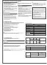
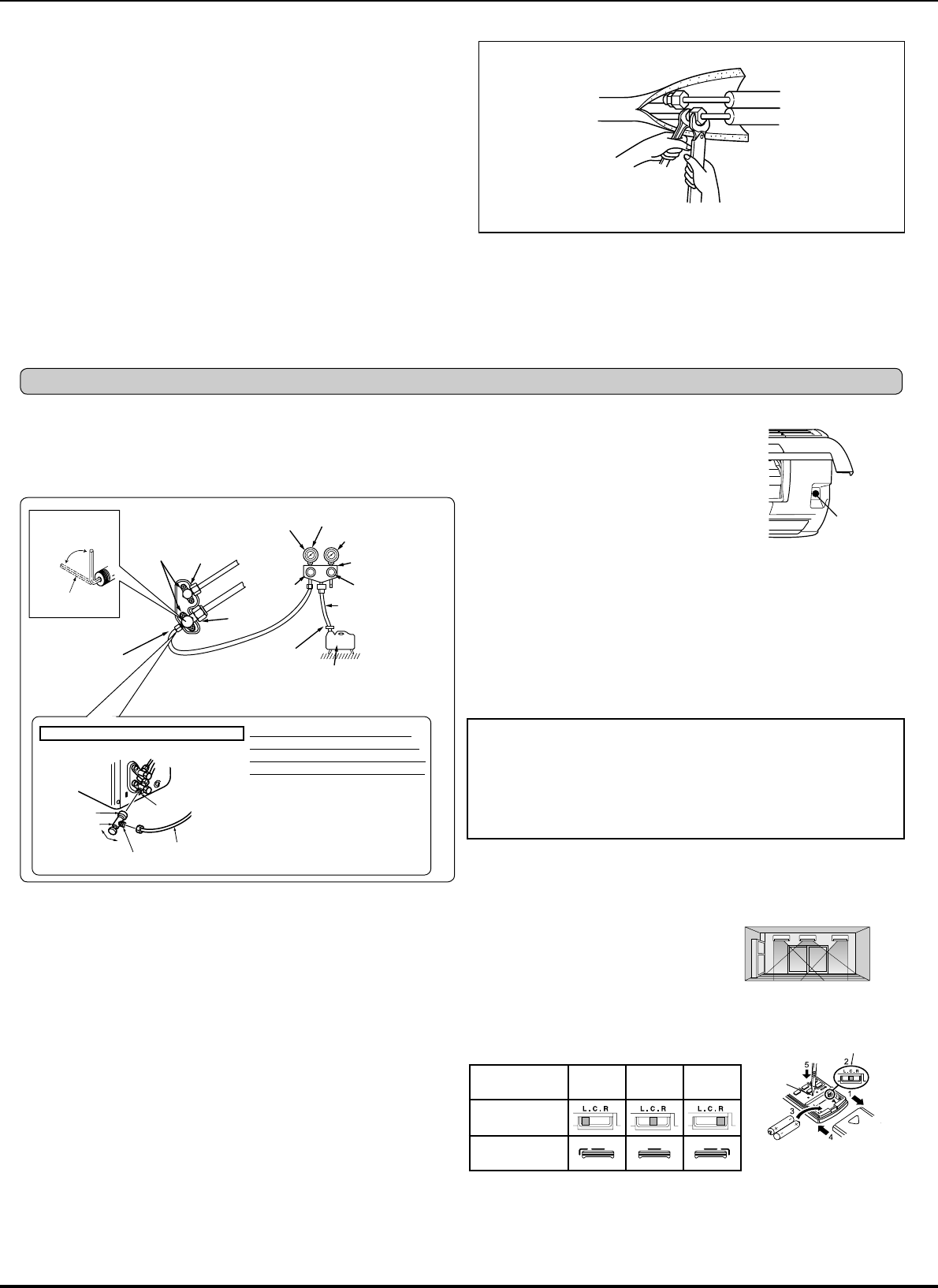
Installation posi-
tion
Left Center Right
Slide switch
Remote controller
display
(Left)(Center)(Right)
RESET
button
SLIDE SWITCH
4-4. REMOTE CONTROLLER SETTING
Set the slide switch of the remote controller according to where the indoor unit is installed
in the area. If the switch is not set correctly, the air conditioner may not function properly.
Location of unit in area:
Left: Distance to objects (wall, cabinet, etc.) is less
than 19-11/16 in. (50 cm) to the left
Center: Distance to objects (wall, cabinet, etc.) is
more than 19-11/16 in. (50 cm) to the left and right
Right: Distance to objects (wall, cabinet, etc.) is less
than 19-11/16 in. (50 cm) to the right
1) Remove the front lid.
2) Set the slide switch according to the installed position of the indoor unit.
3) Insert two (AAA) batteries.
4) Reattach the front lid.
5) Press the RESET button gently using a thin instrument.