


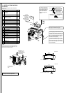
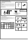
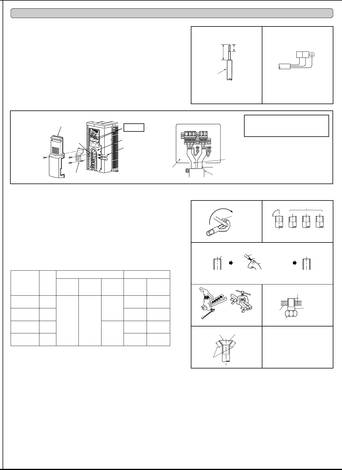
3-1. CONNECTING WIRES FOR OUTDOOR UNIT
1) Remove the service panel.
2) Remove the conduit cover.
3) Attach the conduit connector to conduit plate with lock nut then secure it against unit with
screws.
4) Connect ground wires of indoor/outdoor unit connecting wire (A) and power supply cord (K)
to the TB support.
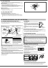
5) Loosen the terminal screw, and attach indoor/outdoor unit connecting wire (A) from the indoor
unit correctly on the terminal block. Attach the wire to the terminal block securely so that its
core cannot be seen, and no external force affects the connecting section of the terminal
block.
6) Firmly tighten the terminal screws. After tightening, verify that the wires are tightly fastened.
7) Connect power supply cord (K).
8) Install the conduit cover.
9) Install the service panel securely.
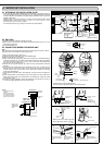
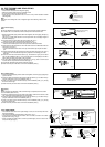
3-2. FLARE CONNECTION
1) Cut the copper pipe as straight as possible with a pipe cutter. (Fig. 1, 2)
2) Remove all burrs from the cut section of the pipe, ensuring that precautions are taken to
avoid getting metal shavings into the piping. (Fig. 3)
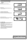
5HPRYHÀDUHQXWVDWWDFKHGWRLQGRRUDQGRXWGRRUXQLWVWKHQSXWWKHPRQSLSH
4) Flaring work (Fig. 4, 5). Firmly hold copper pipe in the dimension shown in the table. Select A
mm from the table according to the tool you use.
5) Check
&RPSDUHWKHÀDUHGZRUNZLWK)LJ
,IÀDUHLVGHIHFWLYHFXWRIIWKHVHFWLRQDQGUHSHDWSURFHGXUH
Terminal block
Conduit cover
Lead wire
3. OUTDOOR UNIT INSTALLATION
Power supply cord (K)
Indoor/outdoor unit
connecting wire (A)
• Make earth wire a little longer than others.
(More than 2-3/8 in. [60 mm])
• For future servicing, leave some slack in
the connecting wires.
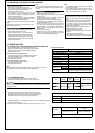
Pipe diameter
inch (mm)
Nut
inch
(mm)
A inch (mm) Tightening torque
Clutch
type tool
for R410A
Clutch
type tool
for R22
Wing nut
type tool
for R22
N•m
ft•lb
(kgf•cm)
ø 1/4 (6.35)
1/4
(17)
0 to 0.02
(0 to 0.5)
0.04 to
0.06
(1.0 to
1.5)
0.06 to
0.08
(1.5 to
2.0)
13.7 to 17.7
10 to 13
(140 to 180)
ø 3/8 (9.52)
3/8
(22)
34.3 to 41.2
25 to 30
(350 to 420)
ø 1/2 (12.7)
1/2
(26)
0.08 to
0.10
(2.0 to
2.5)
49.0 to 56.4
36 to 42
(500 to 575)
ø 5/8 (15.88)
5/8
(29)
73.5 to 78.4
54 to 58
(750 to 800)
Power supply cord (K)
L1
L2
1-3/8 in.
(35 mm)
19/32 in.
(15 mm)
Service panel
Lock nut
Conduit cover
Conduit plate
Connector
Grounding
terminal
Copper
pipe
Good
90°
Tilted
No good
Fig. 1 Fig. 2
Burr
Copper pipe
Spare reamer
Pipe cutter
Fig. 4
Fig. 3
Smooth all around
Even length
all around
Inside is shin
-
ing without any
scratches.
Fig. 5
Fig. 6
A
Flare nut
Die
Copper pipe
Clutch type
Flaring tool
Wing nut type
Uneven Burred
TB support