


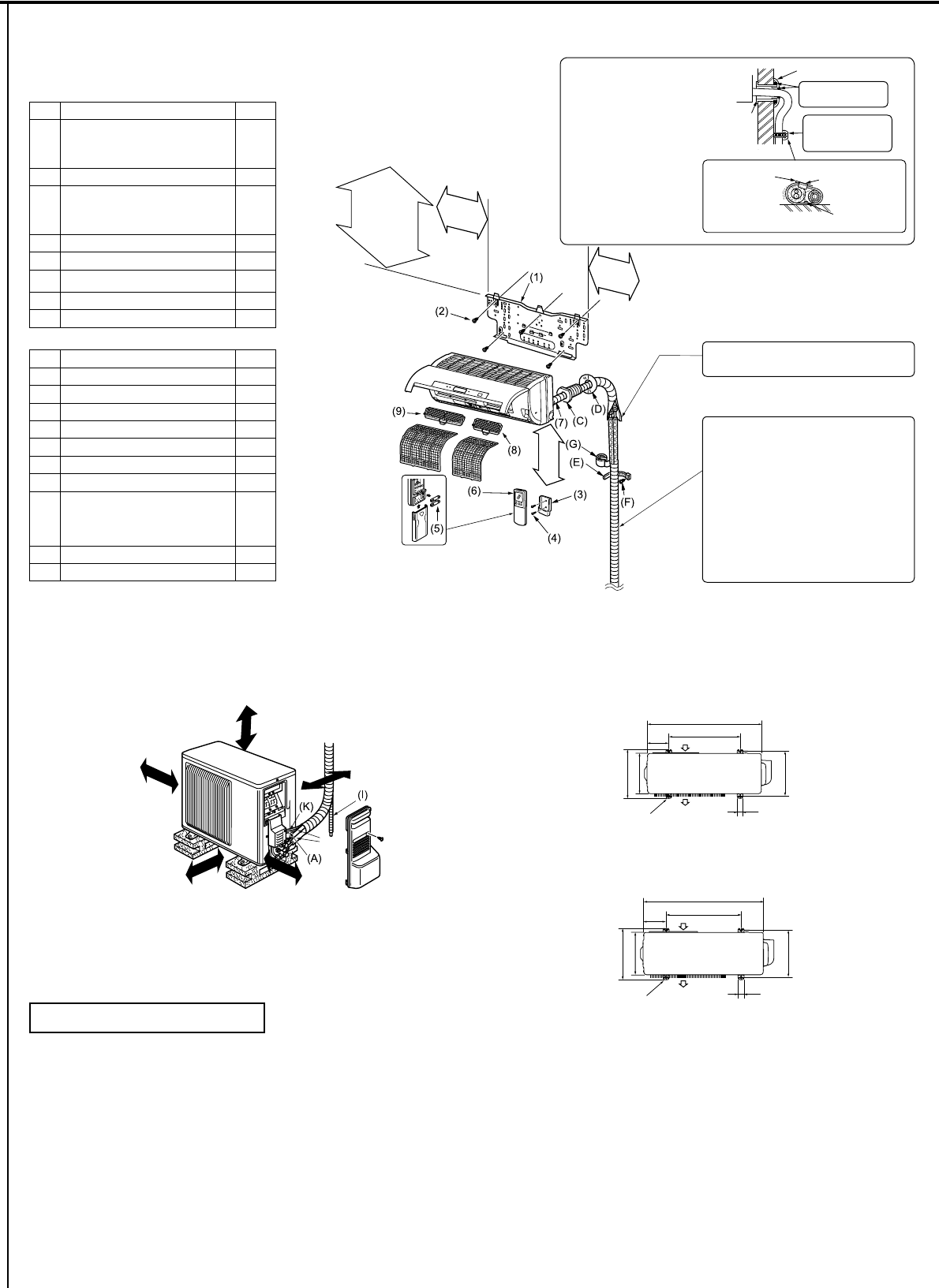
1-4. INSTALLATION DIAGRAM
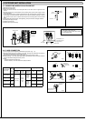
ACCESSORIES
Check the following parts before installation.
<Indoor unit>
(1) Installation plate 1
(2)
Attachment screws for the installa-
tion plate
4×25mm
5
(3) Remote controller holder 1
(4)
Screws for the remote controller
holder
3.5 × 16 mm (Black)
2
(5) Battery (AAA) for (6) 2
(6) Wireless remote controller 1
(7) Felt tape (For left or left-rear piping) 1
(8) Anti-Allergy Enzyme Filter 1
(9) 3ODWLQXPGHRGRUL]LQJ¿OWHU 1
FIELD-SUPPLIED PARTS
(A) Indoor/outdoorunit connecting wire* 1
(B) Extensionpipe 1
(C) Wall hole sleeve 1
(D) Wall hole cover 1
(E) Pipe attachment strap 2 to 5
(F) Screw for (E) 4 × 20 mm 2 to 5
(G) Piping tape 1
(H) Putty 1
(I)
Drain hose
(or soft PVC hose, 19/32 in. [15 mm]
inner diameter or hard PVC pipe
VP16)
2to5
(J) Refrigerant oil 1
(K) Power supply cord 1
Units should be installed by licensed contractor
according to local code requirements.
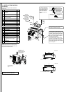
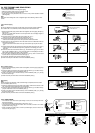
Indoor unit
Wall hole
sleeve (C)
Cut off the
extra length.
Pipe attachment
strap (E)
Use the wall hole sleeve
(C) to prevent indoor/out-
door connecting wire (A)
from contacting metal
parts in the wall and to
protect the wiring from
rodents.
Wall hole cover (D)
Seal the wall hole
gap with putty (H).
Attach the pipe to
wall with pipe at-
tachment strap (E).
Attachment screw (F)
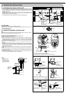
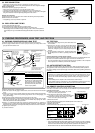
After the leak test, apply insulating mate-
rial tightly so that there is no gap.
When the piping is to be attached to a wall
comprised of tin plate or metal netting, use
chemically treated wooden piece 25/32 in.
(20 mm) or thicker between the wall and
the piping, or wrap insulation vinyl tape 7
to 8 turns around the piping.
To use existing piping, perform COOL
operation for 30 minutes and pump down
before removing the old air conditioner.
5HPDNHÀDUHDFFRUGLQJWRWKHGLPHQVLRQ
for new refrigerant.
* Note:
Place indoor/outdoor unit connecting wire (A)
and power supply cord (K) at least 3 ft. (1 m)
away from the TV antenna wire.
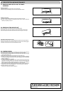
5-5/8 in.(60 mm) or
more/ 2-3/8 in.(142.5
mm) or more for left and
left back piping (using
spacer)
9/32 in. (7 mm)
or more
(B)
Open two sides of
left, right, or rear
side.
4
in.
(100
mm)
or
more
14
in.
(350
mm)
or
more
8
in.
(200
mm)
or
more
Basically open 4 in.
(100 mm) or more
without any obstruction
in front and on both
sides of the unit.
4 in.
(100 mm)
or more
Unit: inch
Unit: mm
31-1/2
19-11/16
Air inlet
Air outlet
13-9/16
11-1/4
2-3/8
×
13/16 slot
12-12-3/4
1-9/16
800
500
Air inlet
Air outlet
2-10
×
21 slot
344.5
285
150
40
304-325
5-
15/16
3-5/16
in.(84
mm)
or
more
3-5/16
in.(84
mm)
or
more