


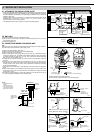
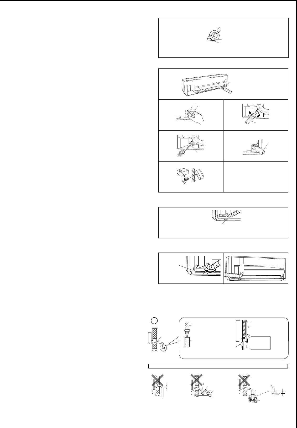
2-4-2. DRAIN PIPING
• If the extension drain hose has to pass through a room, be sure to wrap it with insu-
ODWLRQ¿HOGVXSSOLHG
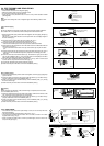
• The drain hose should point downward for easy drain. (Fig. 1)
,IWKHGUDLQKRVHSURYLGHGZLWKWKHLQGRRUXQLWLVWRRVKRUWFRQQHFWLWZLWKD¿HOG
supplied drain hose (I). (Fig. 2)
• When connecting the drain hose to a hard vinyl chloride pipe, be sure to insert it se-
curely into the pipe. (Fig. 3)
Do not make drain piping as shown below.
Do not raise
Accumulated
drain water
Air
Waving
Water
leakage
Water
leakage
Water
leakage
Tip of drain
hose dipped
in water
Ditch
At least
1-31/32 in.
(50 mm)
gap
Downward
slope
Drain
hose
Soft hose I.D.
19/32 in.
(15 mm)
Drain hose
Hard vinyl chloride pipe
I.D. 1-3/16 in.
(30 mm)
Insert
securely
Different
diameter joint
27-9/16 in.
(70 cm)
or more
Fig. 1 Fig. 2 Fig. 3
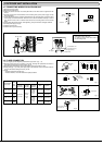
Liquid pipe
Gas pipe
Felt tape (7)
Indoor/outdoor unit
connecting wire (A)
Piping tape (G)
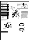
2-4. PIPE FORMING AND DRAIN PIPING
2-4-1. PIPE FORMING
• Place the drain hose below the refrigerant piping.
• Make sure that the drain hose is not crowded or bent.
• Do not pull the hose when applying the tape.
• When the drain hose passes the room, be sure to wrap it with insulation material
¿HOGVXSSOLHG
Note:
Make sure not to damage the cover of refrigerant pipe when attaching it back on with
screws.
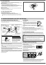
Left or left-rear piping
Note:
Be sure to reattach the drain hose and the drain cap if the piping is being installed on
left or bottom left of unit, otherwise, water could drip down from the drain hose.
3ODFHWKHUHIULJHUDQWSLSLQJDQGWKHGUDLQKRVHWRJHWKHUWKHQ¿UPO\DSSO\IHOWWDSH
from the end.
Felt tape (7) overlap width should be 1/3 the tape width. Use a bandage stopper at
the end of felt tape (7).
2) Pull out the drain cap at the back right of the indoor unit. (Fig. 1)
• Hold the convex section at the end and pull the drain cap.
3) Pull out the drain hose at the back left of the indoor unit. (Fig. 2)
• Hold the claw marked by the arrows and pull out the drain hose forward.
4) Put the drain cap into the section to which the drain hose is to be attached at the rear
of the indoor unit. (Fig. 3)
• Insert a screwdriver into the hole on the cap and insert the cap fully into the drain
pan.
5) Insert the drain hose fully into the drain pan at the back rightof the indoor unit. (Fig. 4)
• Check if the hose is hooked securely to the projection of its inserting part at the
drain pan.
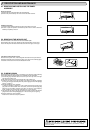
6) Insert the drain hose into wall hole sleeve (C), and attach the upper part of indoor
unit onto the installation plate (1). Then, shift the indoor unit completely to the left to
make placing the piping in the back of the unit easier.
7) Cut out a piece of cardboard from the shipping box, roll it up, hook it onto the back
rib, and use it as a spacer to lift the indoor unit. (Fig. 5)
8) Connect the refrigerant piping with the extension pipe (B).
9) Attach the lower part of the indoor unit into the installation plate (1).
Remove panel for piping
on left side of unit.
Drain cap
Drain hose
Drain cap
Drain hose
Fig. 1 Fig. 2
Fig. 3
Fig. 4
Fig. 5
Piping tape (G)
Felt tape (7)
Rear or bottom piping
3ODFHWKHUHIULJHUDQWSLSLQJDQGWKHGUDLQKRVHWRJHWKHUWKHQ¿UPO\DSSO\SLSLQJWDSH
(G) from the end.
2) Insert the piping and the drain hose into the wall hole sleeve (C), and attach the up-
per part of the indoor unit on the installation plate (1).
3) Check if the indoor unit is attached securely on the installation plate (1) by moving
the unit to left and right.
4) Attach the lower part of the indoor unit into the installation plate (1).
Right piping
Note:
Before performing the following, make sure that wiring is completed, and the conduit
cover is installed. (Refer to 2-3.)
1) Place the refrigerant piping and the drain hose together, shift them to left side of the
XQLWDQGWKHQ¿UPO\DSSO\SLSLQJWDSH*IURPWKHHQG
2) Insert the piping and the drain hose into the wall hole sleeve (C), and attach the up
-
per part of the indoor unit on the installation plate (1).
3) Check if the indoor unit is attached securely on the installation plate (1) by moving
the unit to left and right.
4) Attach the lower part of the indoor unit into the installation plate (1).
To the left
Remove panel
for piping on
right side of
unit
Remove panel for piping on
bottom side of unit