


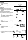
• Connect wires to the appropriate terminals
• For future servicing, leave some slack in the connecting wires.
• Make ground wire a little longer than
others. (More than 1-9/16 in. [40 mm])
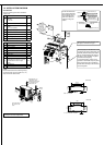
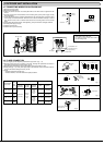
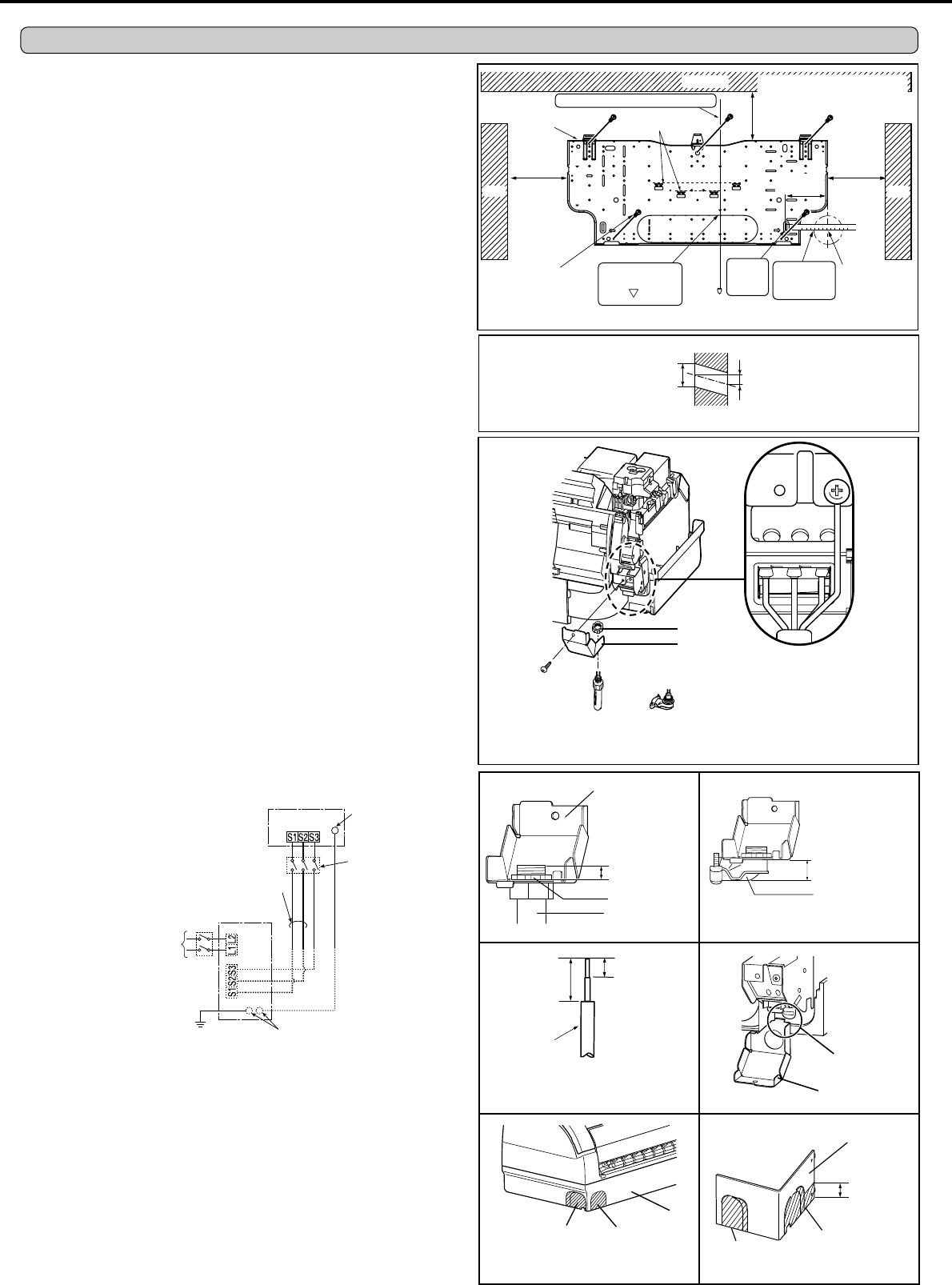
2-1. ATTACHING THE INSTALLATION PLATE
• Find a stud in the wall toattach installation plate (1) horizontally on the wall with screws(2).
• To prevent installation plate (1) from vibrating, be sure to install the attachment screws in
the holes indicated in the illustration. For added support, additional screws may also be
installed in other holes.
• When the indoor unit is to be attached to a concrete wall using recessed bolts, secure
installation plate (1) using 7/16 in. x 13/16 in · 7/16 in. x 1 in. (11 mm × 20 mm · 11 mm ×
26 mm) oval hole (17-3/4 in. [450 mm] pitch).
,IWKHUHFHVVHGEROWLVWRRORQJFKDQJHLWIRUDVKRUWHURQH¿HOGVXSSOLHG
2. INDOOR UNIT INSTALLATION
Wall
Outdoor side
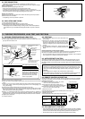
2-2. DRILLING
1) Determine where the holes will be located on the wall.
2) Drill a ø 2-9/16 in. (65 mm) hole. The outdoor side should be 6/32 to 9/32 in. (5 to 7 mm)
lower than the indoor side.
3) Insert wall hole sleeve (C).
2-3. CONNECTING WIRES FOR INDOOR UNIT
Note:
When the indoor unit is powered from the outdoor unit, depending on local code, a discon-
nect switch needs to be installed to a power supply circuit.
1) Remove the panel assembly. (Refer to 5-1.)
2) Place the upper part of the indoor unit on the installation plate.
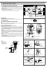
3) Remove corner box and conduit cover.
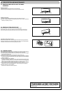
4) Attach conduit pipe (for rear piping) / elbow joint (for right, left, or downward piping) to
conduit cover with lock nut. The thread of the installed conduit pipe / elbow joint appear
-
ing inside should be less than 3/8 in. (10 mm). (Fig. 1) Elbow joint should appear less
than 1-3/16 in. (30 mm) outside. (Fig. 2)
5) Process the end of ground wire (Fig. 3). Connect it to the ground terminal of electrical
parts box.
6) Process the end of indoor/outdoor unit connecting wire (A) (Fig. 3). Attach it to the
terminal block. Be careful not to make mis-wiring. Attach the wire to the terminal block
securely so that its core cannot be seen, and no external force affects the connecting
section of the terminal block.
7) Firmly tighten the terminal screws. After tightening, verify that the wires are tightly fas
-
tened.
8) Secure indoor/outdoor unit connecting wire (A) and the ground wire with conduit cover.
Never fail to hook the claw of the conduit cover to the electrical box. Attach the conduit
cover securely. (Fig. 4)
9) According to the piping direction, remove the shaded part of the left side of box (Fig. 5)
or corner box (Fig.6). Reinstall corner box and front panel.
Less than 3/8 in.
(10 mm)
Conduit cover
Conduit pipe or
elbow joint
Lock nut
6/32-9/32 in.
(5-7 mm)
Ø 2-9/16 in.
(65 mm)
Lead
wire
19/32 in.
(15 mm)
1 in.
(25 mm)
Indoor terminal
block
Fixing
screw
Conduit
cover
Lock nut
or
Conduit pipe
(for rear piping)
Elbow joint
(for right, left, or downward piping)
Elbow joint
(for right, left, or
downward piping)
Less than 1-3/16 in.
(30 mm)
Corner box
Remove panel for
piping on right side of
unit
1 in.
(25 mm)
Remove panel for
piping on bottom side
of unit
Hook
Conduit cover
Fig. 1 Fig. 2
Fig. 3 Fig. 4
Fig. 5 Fig. 6
Box
Remove panel for
piping on left side of
unit
Remove panel for
piping on bottom left
side of unit
Level
Installation plate (1)
Plumb
Align the plumb
line with the
mark .
Center of
ø 2-9/16 in.
(65 mm) hole
3-5/16 in.
(84 mm)
or more
3-5/16 in.
(84 mm)
or more
Bind the line to the center hole.
5-5/8 in. (60 mm) or more
2-3/8 in. (142.5 mm) or more for left
and left back piping (using spacer)
Ceiling
Wall
Wall
Attachment screw (2)
* Same for left hole.
Insert
the
scale. *
Align the
scale with
the line. *
4 in.
(100 mm)
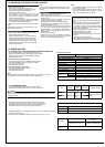
INDOOR UNIT
Terminal block
208/230 V AC
1phase, 60 Hz
Grouding
terminal**
Disconnect
switch*
OUTDOOR UNIT
Grouding terminal**
Ground
Power supply
208/230 V AC,
1phase 2wires.
60 Hz
Terminal
block 1
Remark:
* A disconnectswitch is
required.
Check the local code.
** Use aring tongue termi
-
nal in order to connect a
ground wire to terminal.
Terminal block 2