


33
OPERATING PROCEDURE PHOTOS
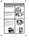
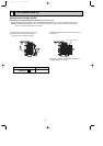
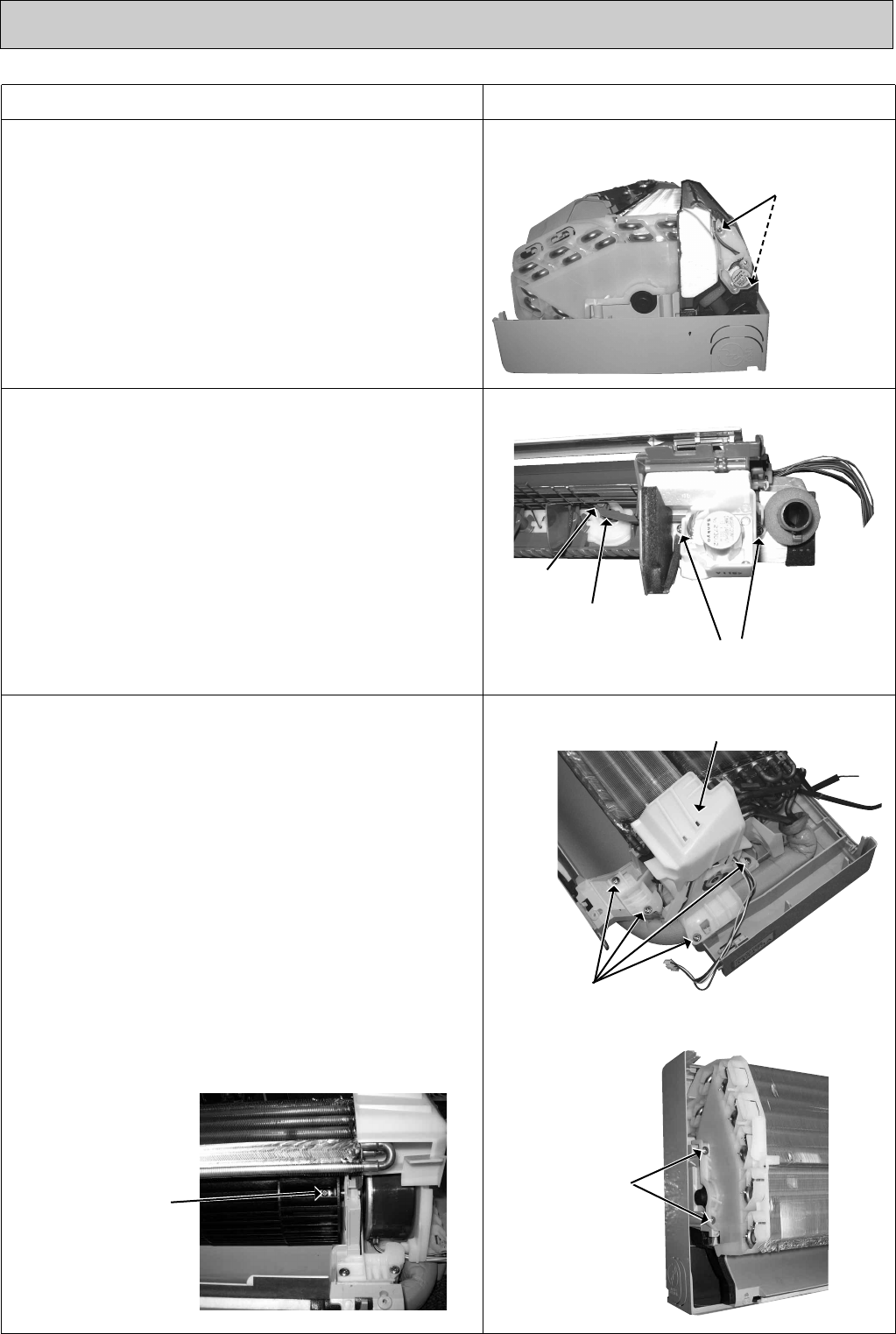
Photo 8
Photo 10
Screws of the
left side of the
heat exchanger
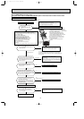
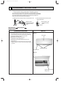
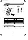
5. Removing the vertical vane motor unit
(1) Remove the horizontal vane, the panel (Refer to 1.) and
the corner box.
(2) Pull out the drain hose from the nozzle assembly, and
remove the nozzle assembly. (See Photo 5.)
(3) Remove the crank of the vertical vane motor unit from the
arm of the vertical vane.(See Photo 7.)
(4) Remove the screws of the vertical vane motor unit, and pull
the vertical vane motor unit. (See Photo 7.)
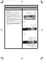
Screws of
the motor
bed
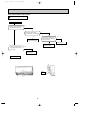
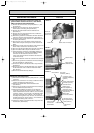
4. Removing the horizontal vane motor unit
(1) Remove the horizontal vane and the panel. (Refer to 1.)
(2) Remove the screws of the horizontal vane motor unit,
and pull out the horizontal vane motor unit. (See Photo 6.)
(3) Disconnect the connector from the horizontal vane motor
unit.
Photo 6
Screw of the horizontal
vane motor unit
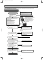
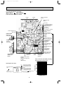
6. Removing the indoor fan motor and the line flow
fan
(1) Remove the horizontal vane, the panel (Refer to 1.) and
the corner box.
(2)
Remove the switch holder and the electrical box. (Refer to 3.)
(3) Pull out the drain hose from the nozzle assembly, and
remove the nozzle assembly.
(4) Remove the screws fixing the motor bed.
(See Photo 8.)
(5) Loosen the screw fixing the line flow fan.
(See Photo 9.)
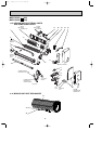
(6) Remove the motor bed together with fan motor and motor
band.
(7) Release the hooks of the motor band, and remove the
motor band then pull out the indoor fan motor.
(8) Remove the screws fixing the left side of the heat
exchanger.
(See Photo 10.)
(9) Lift the heat exchanger, and pull out the line flow fan to the
lower-left.
Photo 9
Screw of
the line
flow fan
Photo 7
Crank of the vertical
vane motor unit
Screws of the vertical
vane motor unit
Arm
Motor band
OB371_--2qxp 05.1.17 12:49 Page 33