


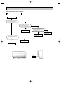
32
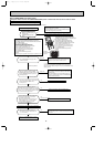
2. Removing the electronic control P.C. board, the
power monitor receiver P.C. board, i-see Sensor,
SW P.C. board and the terminal block
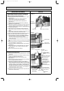
(1) Remove the horizontal vane, the panel (Refer to 1.) and
the corner box.
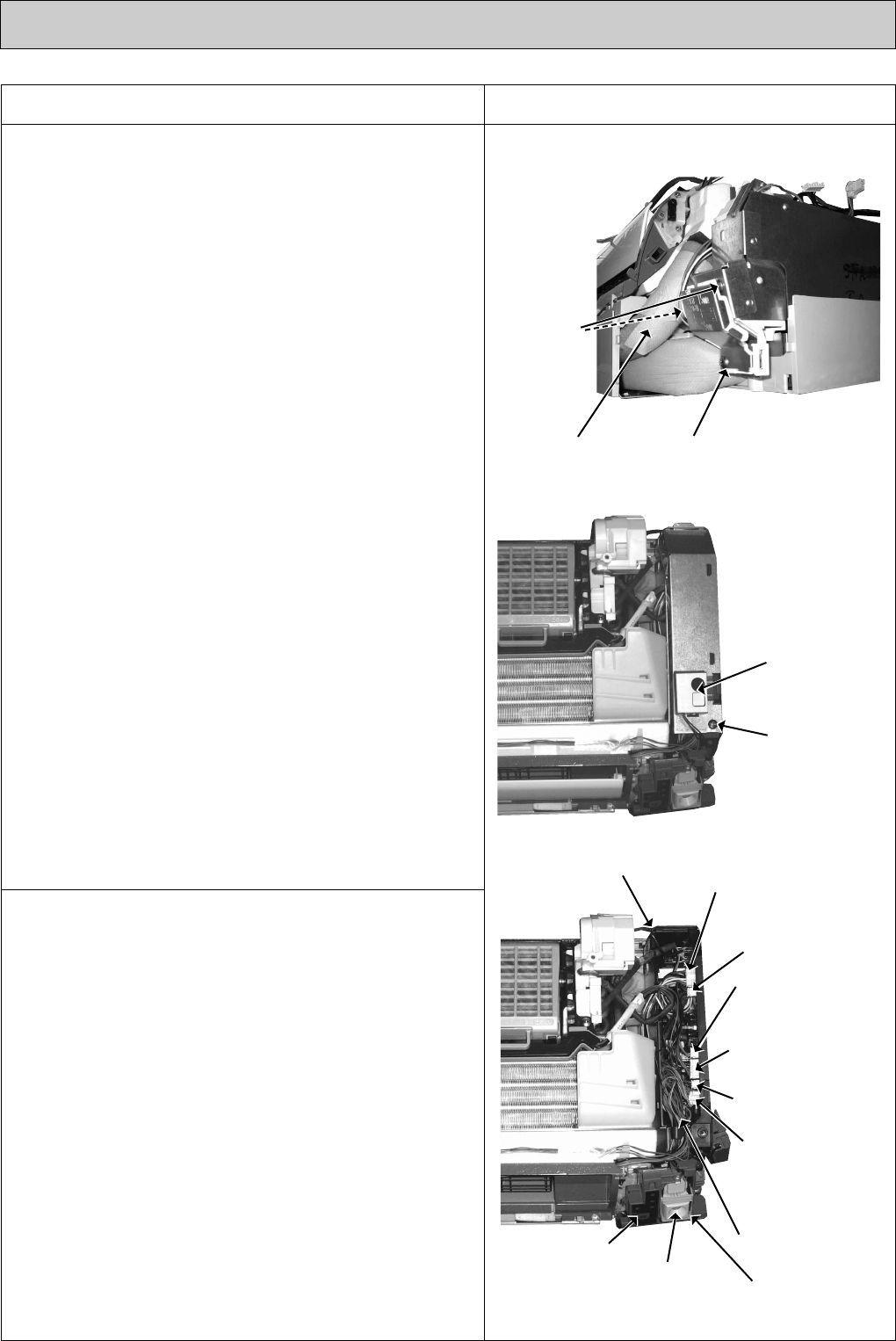
(2) Remove the screw of the V.A. clamp, and then the
indoor/outdoor connecting wire.(See Photo 3.)
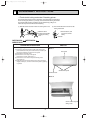
(3) Remove the switch holder from the electrical cover.
(See Photo 4.)
(4) Remove the screw of the electrical cover, and then the
electrical cover. (See Photo 4.)
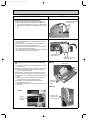
(5) Remove the ground wire connected to the indoor electronic
control P.C. board from the electrical box. (See Photo 5.)
(6) Unhook the power monitor receiver P.C. board holder from
the catch. (See Photo 5.)
(7) Open the rear cover of the power monitor receiver P.C.
board holder and pull out the power monitor receiver P.C.
board.
(8) Remove the screws of the i-see Sensor cover and the i-see
Sensor motor, and then the i-see Sensor motor.
(9) Open the i-see Sensor holder and pull out the i-see Sensor.
(10)
Open the switch holder and pull out SW P.C. board.
(11)
Pull the electronic control P.C. board slightly toward you
from the electrical box, and disconnect TAB3 and all the
connectors on the electronic control P.C. board.
(LD101 and LD105 are direct-mounted to the electronic
control P.C. board.)
(12)
Pull out the electronic control P.C. board from the electrical
box.
(13)
Remove the ground wire connected to the heat exchanger
from the electrical box. (See Photo 5.)
(14)
Unhook the catches of the electrical box, and pull out the
electrical box.
(15)
Remove the screws of the terminal block cover, and then
the terminal block cover and the terminal block holder.
(See Photo 3.)
(16)
Remove the terminal block by sliding it.
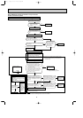
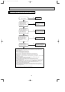
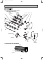
OPERATING PROCEDURE PHOTOS
Screw of the
electrical cover.
Switch holder
Photo 4
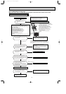
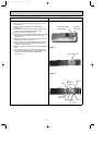
3. Removing the electrical box
(1) Remove the horizontal vane, the panel (Refer to 1.) and the
corner box.
(2) Remove the screw of the V.A. clamp, and then the indoor/
outdoor connecting wire.(See Photo 3.)
(3) Remove the switch holder and the electrical cover.
(See Photo 4.)
(4) Remove the ground wire connected to the heat exchanger
from the electrical box.(See Photo 5.)
(5) Disconnect the following connectors on the electronic
control P.C. board; the fan motor connector <CN211>, the
indoor coil thermistor connector <CN112>, the vane motor
connector <CN151>, the connector of the interlock switch
(Fan) of the horizontal vane <CN1R1>, the connector of
the safety device (plasma unit) <CN1T2>, the connector of
the plasma power P.C. board <CN1T1>, the connector of
the front panel driving motor <CN1U1>.
(6) Unhook the catches of the electrical box, and pull out the
electrical box. (See Photo3.)
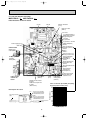
Photo 5
Indoor coil thermistor
connector (CN112)
Fan motor
connector (CN211)
Vane motor
connector (CN151)
Connector of the
front panel driving
motor (CN1U1)
Ground wires
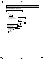
Photo 3
Screws of
the terminal
block cover
Screw of the V.A. clamp
Power monitor
receiver P.C.
board holder
i-see Sensor
Connector of the
interlock switch(Fan)
(CN1R1)
Connector of the
plasma power
P.C.board(CN1T1)
Connector of the
safety device(Plasma
unit) (CN1T2)
Drain hose
i-see Sensor
cover
OB371_--2qxp 05.1.17 12:49 Page 32