


8
GB
D
F
INL
E
PGRRUTR
5. Electrical work
s Consult all related regulations and power companies beforehand.
Warning:
Electrical work should be handled by qualified electric engineers in accord-
ance with all related regulations and attached instruction manuals. Special
circuits should also be used. If there is a lack of power capacity or a defi-
ciency in electrical work, it may cause a risk of electric shock or fire.
s Connect all wires without looseness.
• Fix power source wiring to control box by using buffer bushing for tensile force
(PG connection or the like).
[Fig. 5.0.1] (P.3)
A Control box B Power source wiring
C ø21 hole (closed rubber bushing) D Transmission wiring
s Never connect the power cable to the terminal board for control cables.
(Otherwise it may be broken.)
s Be sure to wire between the control wire terminal boards for indoor unit,
outdoor unit and BC controller.
Transmission cables are of crossover wiring method by non-polarized 2-wires.
Use 2-core shielding cables (CVVS, CPEVS) of more than 1.25 mm
2
in diameter
for transmission cables.
Molded case
circuit breaker
Earth leakage
breaker
6. Setting addresses and operating units
The address switch of each BC controller is set to “000” when shipped from the
factory. Check it.
• Set the address switch to 1 + the address of the outdoor unit.
s The BC controller address should generally be set to 1 + the address of
the outdoor unit. However, if this would result in it having the same ad-
dress as another outdoor unit, set the address between 51 and 100, mak-
ing sure that it is different from the address of other controllers.
• Please refer to the outdoor unit installation manual.
7. Test run
Before getting test run checked
s After installing, piping and wiring the indoor units and BC controllers,
check to see again that there is no refrigerant leakage or no slack on
power and control cables.
s Use a 500 V megger to check that there is an insulation resistance of
more than 1.0 M
Ω between the power terminal bed and the ground. If it is
less than 1.0 M
Ω, do not get operated.
Caution:
Never measure the insulation resistance of the terminal bed for control ca-
bles.
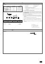
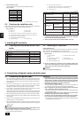
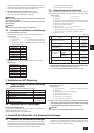
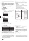
The switch capacity of the main power to BC controllers and the wire size are as
follows:
Switch (A)
Wire size
Capacity Fuse
15 15 20A 20A 30mA 1.5 mm