


3
4.1
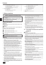
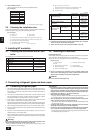
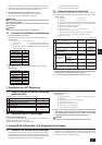
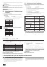
[Fig. 4.1.1]
4
Outdoor
unit side
(Unit: mm)
Piping portion High pressure Low pressure
Item (liquid) side (gas) side
PURY-200
ø25.4 (Brazing)
PURY-P200 ø19.05
PURY-250 (Brazing)
ø28.58 (Brazing)
PURY-P250
Indoor unit side ø9.52 (Flare) ø15.88 (Flare)
A To outdoor unit B End connection (brazing)
C BC controller D Reducer (accessory)
E Indoor unit F Less than 40
G Combined piping kit (Model name: CMY-R160-H)
H Branch pipe (Model name: CMY-Y102S-F)
I Up to three units for 1 branch hole; total capacity: below 80 (but same in cooling/
heating mode)
*1. For connecting 20 to 40 type indoor units
Connect indoor units using the reducers (specials) supplied with BC controllers.
*2. For connecting 100 to 140 type indoor units (or more than a total indoor
unit capacity of 81)
After combining two branch holes using an optionally available combined piping
kit (CMY-R160-H), connect indoor units.
*3. Connection of plural indoor units with one connection (or joint pipe)
• Total capacity of connectable indoor units: Less than 80 (Less than 160 with
joint pipe)
• Number of connectable indoor units: Maximum 3 Sets
• Branch pipe: Use the branch pipe for CITYMULTI Y Series (CMY-Y102S-F)
• Selection of refrigerant piping (Piping size of A/B sections in the above fig-
ure)
Select the size according to the total capacity of indoor units to be installed
downstream.
Total capacity of indoor units Liquid line Gas line
Below 80 ø9.52 ø15.88
81 to 160 ø12.7 ø19.05
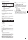
E
EE
EE
I
E
A
B
G
*2
H
*1
D
50-63 100-140 *3
C
*4
F
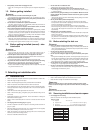
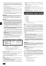
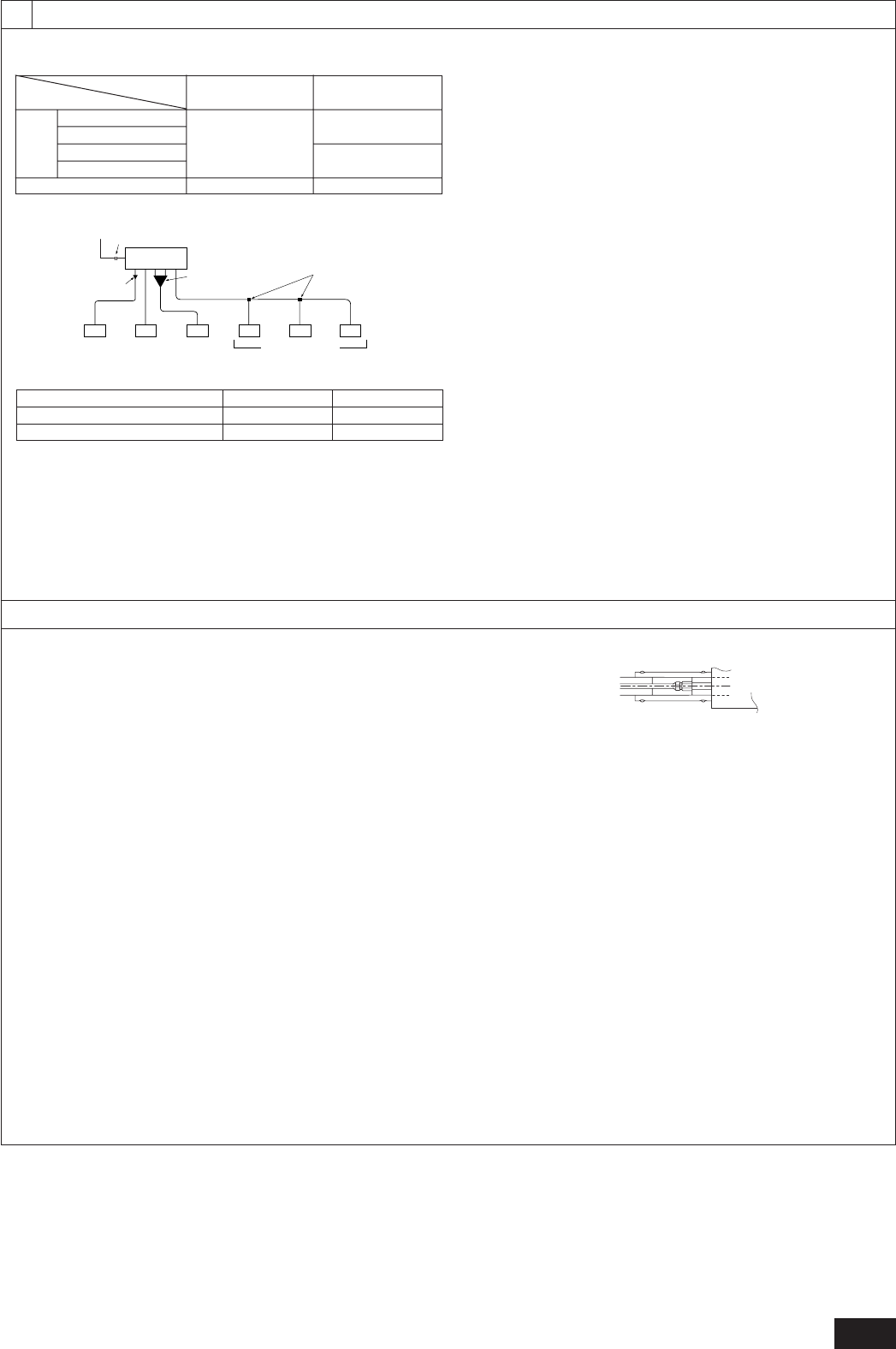
A BC controller
B Locally procured pipe ø28.56
C Locally procured pipe ø25.4
D Refrigerant conn. pipe (accessory)
For PURY-250
PURY-P250
[Fig. 4.1.2]
For PURY-200
PURY-P200
4.2
[Fig. 4.2.1]