


6
GB
D
F
INL
E
PGRRUTR
3. Installing BC controller
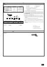
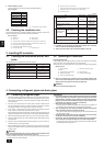
3.1. Checking the accessories with BC con-
troller
The following items are supplied with each BC controller.
Item Qty
1 Drain hose 1
2 Pipe cover for drain hose 1
3 Tie band 2
4 Hose band 1
5 Reducer (large & small) Same number as
branch holes
6 Refrigerant conn. pipe 1
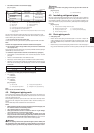
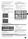
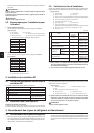
2. When stacking on a rack
(This is a reference view showing the least installation space.)
[Fig. 2.2.2] (P.2)
Model name A
CMB-P104V-F 648
CMB-P105V-F 648
CMB-P106V-F 648
CMB-P108V-F 648
CMB-P1010V-F 648
CMB-P1013V-F 1098
CMB-P1016V-F 1098
A On the side of outdoor unit piping B On the side of indoor unit piping
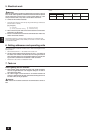
2.3. Checking the installation site
Check that the difference of elevation between indoor and outdoor units and the
length of refrigerant piping are within the following limitations.
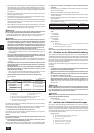
[Fig. 2.3.1] (P.2)
A Outdoor unit B BC controller
C Indoor unit D More than 81
E Less than H=50 m (when the outdoor unit is higher than the indoor unit)
F Less than H1=40 m (when the outdoor unit is lower than the indoor unit)
G Branch pipe (for Y Series) CMY-Y102S-F
J Combined pipe (CMY-R160-HA: optional)
K Less than 70 (60 m) L Less than 30 m
M Up to three units for 1 branch hole
Total capacity: less than 80 (but same in cooling/heating mode)
L Less than h1=15 m (10 m or less for 125, 140 unit type)
M Less than h2=15 m
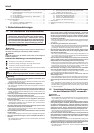
(Unit: m)
Item Piping portion Allowable value
Total piping length
A+B+a+b
Below 220
+c+d+e
Longest piping length A+e
Below 100
(Below 90)*1
Between outdoor and BC
A
Below 70
controllers (Below 60)*1
Between indoor and BC controllers e Below 30
Above outdoor H Below 50
Below outdoor H1 Below 40
Between indoor and BC controllers h1
Below 15
(Below 10)*2
Between indoor and indoor h2
Below 15
(Below 10)*2
Notes:
*1 In the table, if the total capacity of indoor units exceeds 130 % of outdoor
units, it will be the values inside parentheses.
*2 10m or less, with indoor units with model numbers of 125, 140.
Length
Difference of elevation
Between indoor
and outdoor
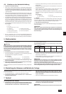
3.2. Installing BC controllers
Installing hanging bolts
Install locally procured hanging bolts (all screws) firmly following the procedure
given in the figure. The hanging bolt size is ø10 (M10 screw).
To hang the unit, use a lifting machine to lift and pass it through the hanging bolts.
[Fig. 3.2.1] (P.2)
1 Hanging method 2 Installing-on-the-floor method
A: Min.30
A Hanging bolt ø10 (field supply) B Nut (field supply)
C Washer (field supply) D Double nuts (field supply)
E Anchor bolt M10 (field supply)
s Be sure to install the BC controllers at level. Installing obliquely may
cause a risk of drain leakage. Use a level to check the unit’s level. If it is
oblique, loosen the fixing nut and make an adjustment.
Caution:
Be sure to install the unit body at level.
4. Connecting refrigerant pipes and drain pipes
4.1. Connecting refrigerant pipes
1. Connect the liquid and gas pipes of each indoor unit to the same end connec-
tion numbers as indicated on the indoor unit flare connection section of each
BC controller. If connected to wrong end connection numbers, there will be no
normal operation.
2. List indoor unit model names in the name plate on the BC controller control
box (for identification purposes), and BC controller end connection numbers
and address numbers in the name plate on the indoor unit side.
3. If the number of connected indoor units is less than the number of branch
holes, it does not matter which end connections you leave.
Seal unused end connections using flare nuts with end caps just as they were
capped when shipped from the factory. No end cap means refrigerant leakage.
4. When using branch pipes (CMY-Y102S-F), be sure to connect them at level.
5. Be sure to tighten the flare nuts using a double spanner. Otherwise the refrig-
erant may leak.
6. Be sure to use non-oxidative brazing where necessary. If you do not use non-
oxidative brazing, it may clog the pipes.
7. After completing pipe connection, support the pipes to prevent that load is
imparted to the BC controller’s end connections (particularly to the gas pipes
of indoor units).
Warning :
When installing and moving the unit, do not charge it with refrigerant other
than the refrigerant (R407C or R22) specified on the unit.
- Mixing of a different refrigerant, air, etc. may cause the refrigerant cycle to mal-
function and result in severe damage.
Caution:
• Use refrigerant piping made of C1220 (CU-DHP) phosphorus deoxidized
copper as specified in the JIS H3300 “Copper and copper alloy seamless
pipes and tubes”. In addition, be sure that the inner and outer surfaces of
the pipes are clean and free of hazardous sulphur, oxides, dust/dirt, shav-
ing particles, oils, moisture, or any other contaminant.
• Never use existing refrigerant piping.
- The large amount of chlorine in conventional refrigerant and refrigerator oil
in the existing piping will cause the new refrigerant to deteriorate.
• Store the piping to be used during installation indoors and keep both
ends of the piping sealed until just before brazing.
- If dust, dirt, or water gets into the refrigerant cycle, the oil will deteriorate and
the compressor may fail.
• Use Suniso 4GS or 3GS (small amount) refrigerator oil to coat the flare
and flange connection part. (For models using R22)
• Use ester oil, ether oil or alkylbenzene (small amount) as the refrigerator
oil to coat flares and flange connections. (For models using R407C)
- The refrigerant used in the unit is highly hygroscopic and mixes with water
and will degrade the refrigerator oil.