


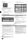

7
GB
D
F
INL
E
PGRRUTR
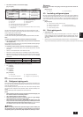
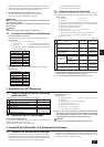
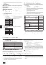
1. Size of BC controller’s end connection piping
[Fig. 4.1.1] (P.3)
(Unit: mm)
Piping portion High pressure Low pressure
Item (liquid) side (gas) side
PURY-200
ø25.4 (Brazing)
PURY-P200 ø19.05
PURY-250 (Brazing)
ø28.58 (Brazing)
PURY-P250
Indoor unit side ø9.52 (Flare) ø15.88 (Flare)
A To outdoor unit B End connection (brazing)
C BC controller D Reducer (accessory)
E Indoor unit F Less than 40
G Combined piping kit (Model name: CMY-R160-H)
H Branch pipe (Model name: CMY-Y102S-F)
I Up to three units for 1 branch hole; total capacity: below 80 (but same in cooling/
heating mode)
The size of BC controller’s branch hole piping is for 50 to 63 type indoor units.
Therefore, if you want to connect indoor units other than the above, do pipe con-
nection following the procedure below.
*1. For connecting 20 to 40 type indoor units
Connect indoor units using the reducers (specials) supplied with BC controllers.
Note:
The flare nuts supplied with BC controllers should be used together.
*2. For connecting 100 to 140 type indoor units (or more than a total indoor
unit capacity of 81)
After combining two branch holes using an optionally available combined piping kit
(CMY-R160-H), connect indoor units.
*3. Connection of plural indoor units with one connection (or joint pipe)
• Total capacity of connectable indoor units: Less than 80 (Less than 160 with
joint pipe)
• Number of connectable indoor units: Maximum 3 Sets
• Branch pipe: Use the branch pipe for CITYMULTI Y Series (CMY-Y102S-F)
• Selection of refrigerant piping (Piping size of A/B sections in the above figure)
Select the size according to the total capacity of indoor units to be installed
downstream.
Total capacity of indoor units Liquid line Gas line
Below 80 ø9.52 ø15.88
81 to 160 ø12.7 ø19.05
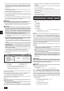
2. Connecting to outside pipes (low pressure side pipes)
• For PURY-250
PURY-P250
[Fig. 4.1.2] (P.3)
• For PURY-200
PURY-P200
[Fig. 4.1.2] (P.3)
A BC controller B Locally procured pipe ø28.58
C Locally procured pipe ø25.4 D Refrigerant conn. pipe (accessory)
Note:
Be sure to use non-oxidative brazing.
4.2. Refrigerant piping work
After connecting the refrigerant pipes of all indoor and outdoor units with the out-
door units’ stop valves remained fully closed, evacuate vacuum from the outdoor
units’ stop valve service ports.
After completing the above, open the valve rods of the indoor units’ stop valves.
This connects the refrigerant circuit (between outdoor and BC controller) com-
pletely.
How to handle stop valves is described on each outdoor unit.
Notes:
• Before tightening the flare nut, apply refrigerating machine oil lightly over
the valve flare surface and its seating surface.
• Use a double spanner for pipe connection.
• After pipe connection, be sure to check that there is no gas leakage,
using a leak detector or soap-and-water solution.
• Before brazing the refrigerant piping, always wrap the piping on the main
body, and the thermal insulation piping, with damp cloths to prevent heat
shrinkage and burning the thermal insulation tubing. Take care to ensure
that the flame does not come into contact with the main body itself.
Warning:
Do not mix anything other than the specified refrigerant (R-22 or R407C) into
the refrigerating cycle when installing or moving. Mixing air may cause the
refrigerating cycle to get abnormally high temperature, resulting in a burst.
Outdoor
unit side
Caution:
Cut the tip of the indoor unit piping, remove the gas, and then remove the
brazed cap.
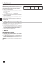
[Fig. 4.2.1] (P.3)
A Cut here B Remove brazed cap
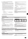
4.3. Insulating refrigerant pipes
Be sure to wind heat-resisting polyethylene form of more than 10mm in thickness
onto both liquid and gas pipes and also put it into the joints between indoor unit
and insulating material so that there will be no gap. Incomplete insulation may
cause a risk of dew drop. Pay careful attention, particularly when insulating above
the ceiling.
[Fig. 4.3.1] (P.3)
A Locally procured insulating material for pipes
B Bind here using band or tape. C Do not have any opening.
D Lap margin: more than 40 E Insulating material (field supply)
F Unit side insulating material
4.4. Drain piping work
1. Drain piping work
• Ensure that the drain piping is downward (pitch of more than 1/100) to the
outdoor (discharge) side. If it is impossible to take any downward pitch, use an
optionally available drain-up mechanism to obtain a downward pitch of more
than 1/100.
• Ensure that any cross-wise drain piping is less than 20 m. If the drain piping is
long, provide metal braces to prevent it from waving. Never provide ipine Twrf more tuv8.6( If iOe wi dr)13(a7 pipi2.7(ork)yno gejected./F6 1 Tf0 -1143 -1.7143 TD0 Tw()Tj/F1 1 Tf1.7143 0 TD-0.037 T8[(outdConnect dr)8ly))insu3(ai Ne)pipihosethe