


9
B
G
H
C
A
F
E
D
I
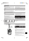
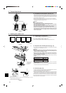
Fig. 5-6
1
2
5. Installing the refrigerant piping
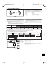
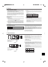
5.5. Stop valve opening method (Fig. 5-6)
(1)Remove the cap and turn the valve rod counterclockwise as far as it will go with
the use of hexagonal wrench. Stop turning when it hits the stopper.
(2)Make sure that the stop valve is open completely, push in the handle and rotate
the cap back to its original position.
A Valve
B Unit side
C Open
D Cap
E Local pipe side
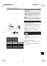
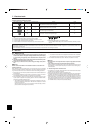
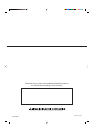
5.6. Addition of refrigerant (Fig. 5-7)
• Additional charging is not necessary for this unit if the pipe length does not exceed
30 m.
• If the pipe length exceeds 30 m, charge the unit with additional R410A refrigerant
according to the permitted pipe lengths in the chart below.
* When the unit is stopped, charge the unit with the additional refrigerant through
the liquid stop valve after the pipe extensions and indoor unit have been
vacuumized.
When the unit is operating, add refrigerant to the gas check valve using a
safety charger. Do not add liquid refrigerant directly to the check valve.
* After charging the unit with refrigerant, note the added refrigerant amount on
the service label (attached to the unit).
Refer to the “1.5. Using R410A refrigerant air conditioners” for more informa-
tion.
• Be careful when installing multiple units. Connecting to an incorrect indoor unit can
lead to abnormally high pressure and have a serious effect on operation perform-
ance.
A+B+C+D
Amount of additional refrigerant charge (kg)
30 m and less 31-40 m and less 41-50 m and less 51-60 m and less 61-70 m and less 71-120 m and less
0.9 kg 1.8 kg 2.7 kg 3.6 kg
1.2 kg 2.4 kg 3.6 kg 4.8 kg
Outdoor unit
RP200
RP250
At time of shipping
(kg)
10.5
10.5
No additional
charge necessary
Calculate the amount of
additional refrigerant
charge using formula
provided below.
Main piping:
Liquid line size
ø9.52 overall length ×
0.09 (Gas line: ø28.58)
(m) × 0.09 (kg/m)
Branch piping: Liquid
line size
ø9.52 overall length ×
0.06 (Gas line: ø15.88)
(m) × 0.06 (kg/m)
Branch piping: Liquid
line size
ø6.35 overall length ×
0.02 (Gas line: ø15.88)
(m) × 0.02 (kg/m)
3.6 (kg)
Amount of additional
charge
(kg)
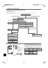
Main piping:
Liquid line size
ø12.7 overall length ×
0.12
(m) × 0.12 (kg/m)
+++–=
Additional charge amount
for 70 meters
RP200 3.6 kg
RP250 4.8 kg
When length exceeds 70 m
When the total length of the piping exceeds 70 m, calculate the amount of additional charge based on the following requirements.
Note: If the calculation produces a negative number (i.e. a “minus” charge), of if calculation results in an amount that is less than the “Additional charge amount for 70 m,”
perform the additional charge using the amount shown in “Additional charge amount for 70 m.”
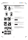
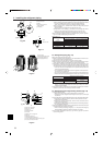
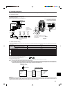
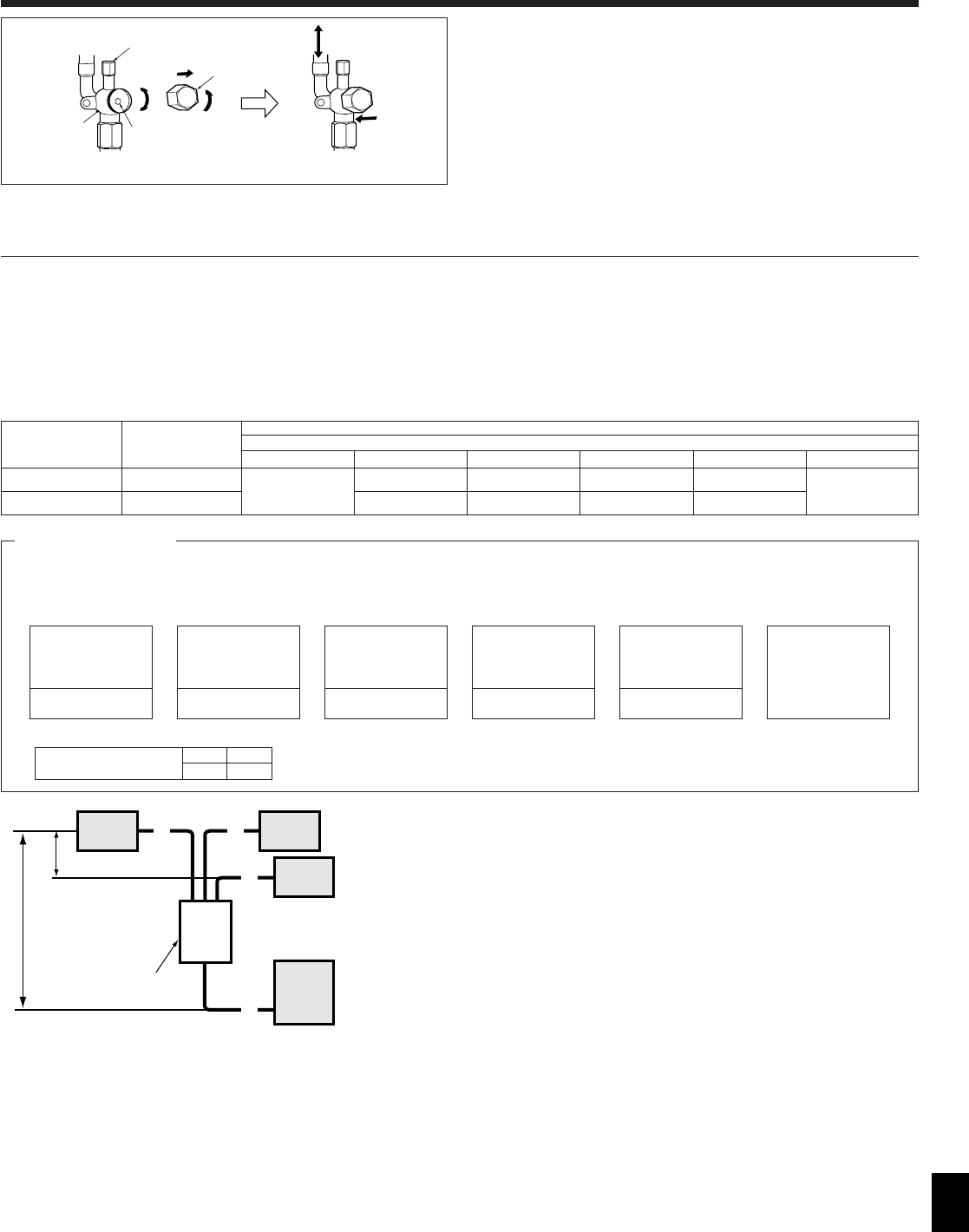
Fig. 5-7
1 Indoor unit
2 Outdoor unit
3 Main piping
4 Branch piping
5 Multi distribution
pipe (option)
Outdoor unit : RP250 A: ø12.7 ... 65 m
Indoor unit 1 : RP71 B: ø9.52 ... 5 m
Indoor unit 2 : RP71 C: ø9.52 ... 5 m
Indoor unit 3 : RP71 D: ø9.52 ... 5 m
Main piping ø12.7 is A = 65 m
Branch piping ø9.52 is B + C + D = 15 m
Therefore, the amount of additional charge is: 65 × 0.12 + 15 × 0.06 -3.6=5.1 (kg)
(Fractions are rounded up)
F Close
G Service port
H Wrench hole
Liquid side : 4 mm hexagonal wrench
Gas side : 10 mm hexagonal wrench
D
A
H
B C
11
1
44
4
5
3
2
Max. 1m