


14
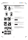
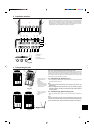
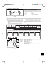
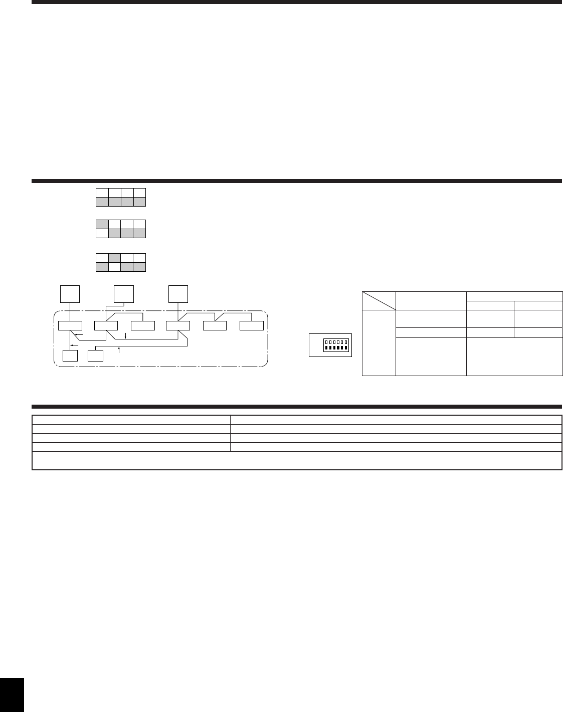
10. System control (Fig. 10-1)
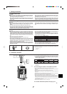
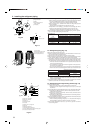
9.3. Refrigerant collecting (pump down)
Perform the following procedures to collect the refrigerant when moving the indoor
unit or the outdoor unit.
1 Before collecting the refrigerant, first make sure that the all of the SW5 DIP switches
for function changes on the control board of the outdoor unit are set to OFF. If all of the
SW5 switches are not set to OFF, record the settings and then set all of the switches
to OFF. Start collecting the refrigerant. After moving the unit to a new location and
completing the test run, set the SW5 switches to the previously recorded settings.
2 Supply power (circuit breaker).
* When power is supplied, make sure that “CENTRALLY CONTROLLED” is not
displayed on the remote controller. If “CENTRALLY CONTROLLED” is dis-
played, the refrigerant collecting (pump down) cannot be completed normally.
3 After the liquid stop valve is closed, set the SWP switch on the control board of the
outdoor unit to ON. The compressor (outdoor unit) and ventilators (indoor and
outdoor units) start operating and refrigerant collecting operation begins. LED1
and LED2 on the control board of the outdoor unit are lit.
* Set the refrigerant address using the DIP switch of the outdoor unit.
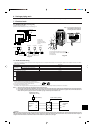
1 Wiring from the Remote Control
This wire is connected to TB5 (terminal board for remote controller) of the indoor unit
(non-polar).
2 When a Different Refrigerant System Grouping is Used.
Up to 16 refrigerant systems can be controlled as one group using the slim MA re-
mote controller.
Note:
In single refrigerant system (twin/triple/quadruple), there is no need of wiring
2.
A Outdoor unit
B Indoor unit
C Master remote controller
D Subordinate remote controller
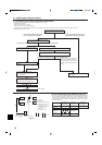
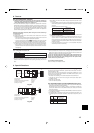
E Standard 1:1 (Refrigerant address = 00)
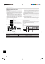
F Simultaneous twin (Refrigerant address = 01)
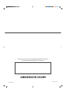
G Simultaneous triple (Refrigerant address = 02)
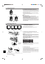
ON
OFF
3456
E SW 1 - 3 ~ 6
ON
OFF
3456
F SW 1 - 3 ~ 6
ON
OFF
3456
G SW 1 - 3 ~ 6
Operation according to switch setting
ON OFF
Start Normal
Clear Normal
Settings for outdoor unit ad-
dresses 0 to 15
SW1
Function table
<SW1>
Function
1 Compulsory de-
frosting
2 Error history clear
3
4
5
6
ON
123456
OFF
TB4
TB5
TB1
TB4
TB5
TB4
TB1
TB4
TB1
TB4TB4
TB5
1
1
2
2
AA
BBBBBB
CD
AFGE
SW1
function
settings
Fig. 10-1
Refrigerant sys-
tem address set-
ting
* Only set the SWP switch (push-button type) to ON if the unit is stopped. How-
ever, even if the unit is stopped and the SWP switch is set to ON less than
three minutes after the compressor stops, the refrigerant collecting operation
cannot be performed. Wait until compressor has been stopped for three min-
utes and then set the SWP switch to ON again.
4 Because the unit automatically stops in about two to three minutes after the refrig-
erant collecting operation (LED1 and LED2 are lit), be sure to quickly close the
gas stop valve. When LED1 and LED2 are lit and the outdoor unit is stopped, open
the liquid stop valve completely, and then repeat step 3 after three minutes have
passed.
* If the refrigerant collecting operation has been completed normally (LED1 and
LED2 are lit), the unit will remain stopped until the power supply is turned off.
5 Turn off the power supply (circuit breaker).
* Note that when the length of the extension piping is long, it may not be possi-
ble to perform a pump-down operation. When performing the pump-down op-
eration, make sure that the low pressure is lowered to near 0 MPa (gauge).
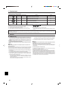
11. Information on rating plate
Model
Refrigerant (R410A) kg
Allowable pressure (Ps)
Net weight kg
RP200, 250
10.5
HP:3.6 MPa (36 bar), LP:2.3 MPa (23 bar)
198
MANUFACTURER: MITSUBISHI ELECTRIC CORPORATION, SHIZUOKA WORKS
18-1, OSHIKA 3-CHOME, SURUGA-KU, SHIZUOKA CITY, JAPAN
9. Special Functions