


12
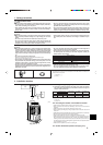
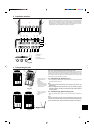
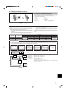
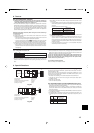
WIRING SPECIFICATIONS FOR 220-240 V 50 Hz
(INDOOR-OUTDOOR CONNECTING CABLE)
Cross section of cable
Round
Flat
Flat
Round
Wire size (mm
2
)
2.5
2.5
1.5
2.5
Number of wires
3
3
4
4
Polarity
Clockwise : S1-S2-S3
* Pay attention to stripe of yellow and green
Not applicable
(Because center wire has no cover finish)
From left to right : S1-Open-S2-S3
Clockwise : S1-S2-S3-Open
*Connect S1 and S3 to the opposite angle
L (m)*6
(30)
*2
Not applicable
*5
(18)
*3
(30)
*4
*1 :Power supply cords of appliances shall not be lighter than design 245 IEC or 227
IEC.
*2 :In case that cable with stripe of yellow and green is available.
*3 :In case of regular polarity connection (S1-S2-S3), wire size is 1.5 mm
2
.
*4 :In case of regular polarity connection (S1-S2-S3).
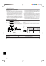
*5 :In the flat cables are connected as this picture, they can be used up to 30 m.
*6 :Mentioned cable length is just a reference value.
It may be different depending on the condition of installation, Humidity or materi-
als, etc.
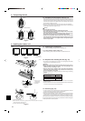
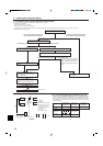
S1 S2 S3
(3C Flat cable × 2)
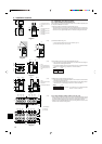
Be sure to connect the indoor-outdoor connecting cables directly to the units (no intermediate connections).
Intermediate connections can lead to communication errors if water enters the cables and causes insufficient insulation to ground or a poor electrical contact at the
intermediate connection point.
(If an intermediate connection is necessary, be sure to take measures to prevent water from entering the cables.)
7. Electrical work
8. Test run
8.1. Before test run
s After completing installation and the wiring and piping of the indoor and
outdoor units, check for refrigerant leakage, looseness in the power supply
or control wiring, wrong polarity, and no disconnection of one phase in the
supply.
s Use a 500-volt M-ohm tester to check that the resistance between the power
supply terminals and ground is at least 1 MΩ.
s Do not carry out this test on the control wiring (low voltage circuit) termi-
nals.
Warning:
Do not use the air conditioner if the insulation resistance is less than 1 MΩ.
Insulation resistance
After installation or after the power source to the unit has been cut for an extended
period, the insulation resistance will drop below 1 MΩ due to refrigerant accumulat-
ing in the compressor. This is not a malfunction. Perform the following procedures.
1. Remove the wires from the compressor and measure the insulation resistance of
the compressor.
2. If the insulation resistance is below 1 MΩ, the compressor is faulty or the resist-
ance dropped due the accumulation of refrigerant in the compressor.
3. After connecting the wires to the compressor, the compressor will start to warm
up after power is supplied. After supplying power for the times indicated below,
measure the insulation resistance again.
• The insulation resistance drops due to accumulation of refrigerant in the com-
pressor. The resistance will rise above 1 MΩ after the compressor is warmed
up for two to three hours.
(The time necessary to warm up the compressor varies according to atmos-
pheric conditions and refrigerant accumulation.)
• To operate the compressor with refrigerant accumulated in the compressor,
the compressor must be warmed up at least 12 hours to prevent breakdown.
4. If the insulation resistance rises above 1 MΩ, the compressor is not faulty.
Caution:
• The compressor will not operate unless the power supply phase connection
is correct.
• Turn on the power at least 12 hours before starting operation.
- Starting operation immediately after turning on the main power switch can result in
severe damage to internal parts. Keep the power switch turned on during the op-
erational season.
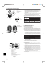
s The followings must be checked as well.
• The outdoor unit is not faulty. LED1 and LED2 on the control board of the outdoor
unit flash when the outdoor unit is faulty.
• Both the gas and liquid stop valves are completely open.
• A protective sheet covers the surface of the DIP switch panel on the control board of
the outdoor unit. Remove the protective sheet to operate the DIP switches easily.
• Make sure that the all of the SW5 DIP switches for function changes on the control
board of the outdoor unit are set to OFF. If all of the SW5 switches are not set to
OFF, record the settings and then set all of the switches to OFF. Begin recovering
the refrigerant. After moving the unit to a new location and completing the test run,
set the SW5 switches to the previously recorded settings.