


11
7. Electrical work
Fig. 7-1
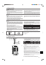
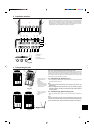
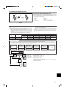
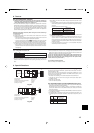
7.1. Outdoor unit (Fig. 7-1, Fig. 7-2)
(1) Remove the service panel.
(2) Wire the cables referring to the Fig. 7-1 and the Fig. 7-2.
A Indoor unit
B Outdoor unit
C Remote controller
D Main switch (Breaker)
E Earth
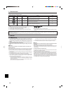
Indoor unit model
Phase
Outdoor unit
Frequency & Voltage
Power supply
Max. Permissive System Impedance (Ω)
Outdoor unit input capacity *1
Main switch (Breaker)
Outdoor unit power supply
Outdoor unit power supply earth
Indoor unit-Outdoor unit *2
Indoor unit-Outdoor unit earth
Remote controller-Indoor unit *3
Outdoor unit L1-N, L2-N, L3-N
Indoor unit-Outdoor unit S1-S2 *4
Indoor unit-Outdoor unit S2-S3 *4
Remote controller-Indoor unit *4
Wiring
Wire No. ×
size (mm
2
)
Circuit
rating
RP200, 250
3N~(3ph 4-wires), 50Hz,
380-400-415V
0.25
32A
4 × Min. 6
1 × Min. 6
Cable length 50 m : 3 × 4 (Polar)/Cable length 80 m : 3 × 6 (Polar)
1 × Min. 2.5
2 × 0.69 (Non-polar)
AC 220-230-240V
AC 220-230-240V
DC24V
DC14V
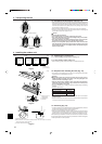
*1. A breaker with at least 3 mm contact separation in each pole shall be provided. Use non-fuse breaker (NF) or earth leakage breaker (NV).
*2. Max. 80 m Total Max. including all indoor/indoor connection is 80 m.
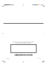
• Use one cable for S1 and S2 and another for S3 as shown in the picture.
*3. A 10 m wire is attached in the remote controller accessory.
*4. The voltage are NOT against the ground.
S3 terminal has DC 24 V against S2 terminal. However between S3 and S1, these terminals are not electrically insulated by the transformer or other device.
Notes: 1. Wiring size must comply with the applicable local and national code.
2. Power supply cords and Indoor unit/Outdoor unit connecting cords shall not be lighter than polychloroprene sheathed flexible cord. (Design 245 IEC 57)
3. Use an earth wire which is longer than the other cords so that it will not become disconnected when tension is applied. The earth wire should also be
thicker than the power supply cord so that it can stand any surge of electricity when trouble occurs.
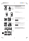
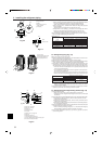
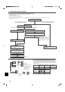
7.2. Field electrical wiring
• If the wiring connecting the indoor and outdoor units is longer than 80 m, use separate indoor/outdoor unit power supplies. (Refer to the installation manuals of the indoor
units for more information.)
For Heater
*With Heater
model only
For Power
For Power
For Heater For Heater For Heater
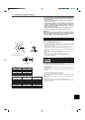
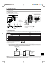
6. Drainage piping work
It is possible to have the drain flow out along the bottom of the outdoor unit. Use the centralized drainage kit when using drain piping.
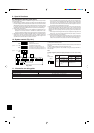
F Power supply terminal block (L1, L2, L3, N, )
G Indoor/outdoor connection terminal block (S1, S2, S3)
H Service panel
J Protective sheet
Fig. 7-2
A
C
D
B
S3
S3
S2
S1
N
L
S2S1L3
L2L1 N
D
D
E
EEE
C
B
A
D D D
A
EE
D
AA
F
H
J
G
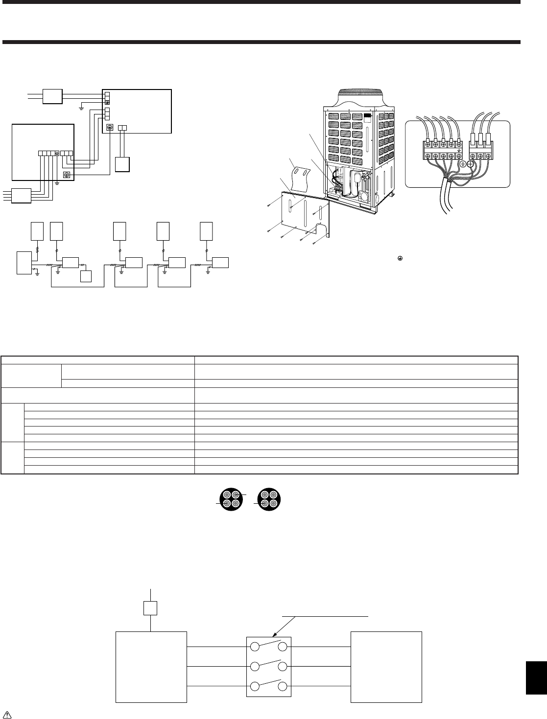
380/400/415V 50Hz
Three phase (4 wires)
Isolator (Switch)
“A-Control”
Outdoor
Unit
“A-Control”
Indoor
Unit
3 poles isolator (Switch)
S1
S2
S3
S1
S2
S3
Warning:
In case of A-control wiring, there is high voltage potential on the S3 terminal caused by electrical circuit design that has no electrical insulation between power line
and communication signal line. Therefore, please turn off the main power supply when servicing. And do not touch the S1, S2, S3 terminals when the power is
energized. If isolator should be used between indoor unit and outdoor unit, please use 3-poles type.
For Heater
Note: If the protective sheet for the
electrical box is removed during
servicing, be sure to reinstall it.
L3L2L1
N
S1 S2 S3
S1
S2
S3