


6
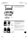
3. Transporting the unit
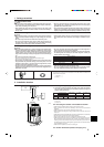
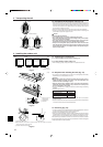
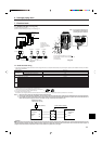
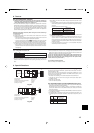
3.3. Precautions when lifting the unit (Fig. 3-3)
• When hang-lifting the unit, pass the sling or rope through the square-shaped holes
(there are 4) at the base. The rope must go up along the unit to the top as shown in
the picture. Please put small cushions between ropes and the unit (where the ropes
touch the unit) to protect the unit (plastic part) from any damages. (The rope can
cause scratches or dents to the unit.)
• Make sure that the angles between ropes (at the top) are less that 40 degrees.
• Always use 2 ropes to lift up the unit. Each rope must be at least 7 metres long and
must be able to support the weight of the unit.
Caution:
Precautions When Transporting
• Units weighing 20 kg or more shall not be lifted by one person.
• Never touch the finned surface of the heat exchanger with your bare hands.
This area can cause cuts or damage.
• Never allow children to play with the plastic bag used for covering the unit.
Asphyxiation could occur. Always cut up the bag before disposing.
• Always use the designated spaces provided at the base of the unit when
lifting the unit. Make sure that four support points are always used. The unit
will be unstable and tip over or be dropped if lifted or transported using less
than four support points.
Fig. 3-3
4. Installing the outdoor unit
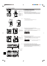
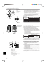
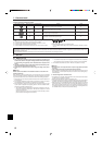
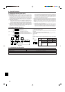
4.1. Positioning the anchor bolts
4.1.1. When installing a single outdoor unit (Fig. 4-1)
4.1.2. When installing multiple outdoor unit
• When installing in groups, always provide 90 mm of space between units.
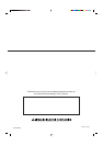
4.2. Requests when installing the units (Fig. 4-2)
• Do not block the air passageways for the unit. If the air passageways are blocked,
trouble could occur in the operation of the unit.
Warning:
• Always make certain that the surface onto which the unit is going to be in-
stalled has sufficient strength. If the surface is not strong enough, the unit
could fall over and cause damage or injury.
• Make sure that the unit is installed so that it will be able to withstand earth-
quakes and strong winds. Damage or injury could occur if the unit tips over
due to an earthquake or strong wind.
• Be sure to install the unit in a sturdy, level surface to prevent rattling noises during
operation.
<Foundation specifications>
Foundation bolt M10 (J type)
Thickness of concrete 120 mm
Length of bolt 70 mm
Weight-bearing capacity 320 kg
• Make sure that the length of the foundation bolt is within 40 mm of the bottom
surface of the base.
• Secure the base of the unit firmly with four-M10 foundation bolts in sturdy locations.
* Procure the anchor bolts, nuts and washers locally.
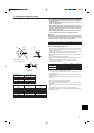
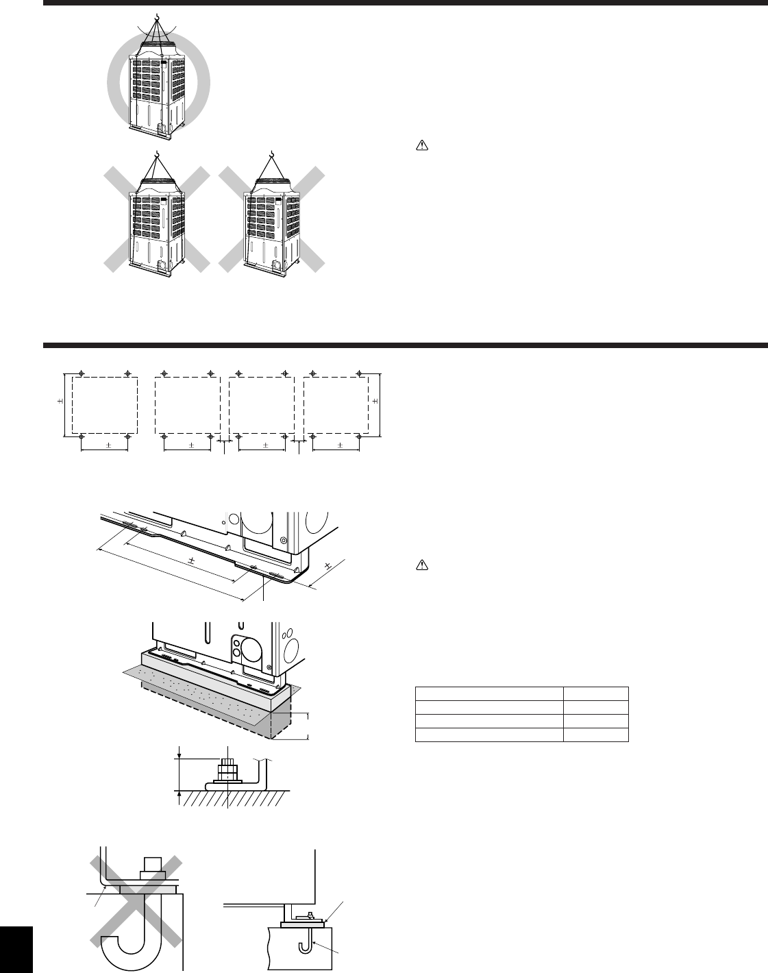
4.3. Anchoring (Fig. 4-3)
• In order to enable the unit to withstand strong winds and earthquakes, make sure
that the anchor bolts are installed as shown in the illustration.
• Provide a strong foundation of concrete or angle iron.
• With some types of installation, vibration will be conveyed along the base to floors
and walls where it could create noise. In such locations, take measures to prevent
vibration (such as using anti-vibration pads or suspension mounting for the unit).
When performing the foundation work make sure that the floor surface has sufficient
strength and carefully route piping and wiring in consideration of water drainage that
will be required when the unit is operated.
Fig. 4-1
Fig. 4-2
Fig. 4-3
Prohibited installation
560 5 560 5560 5560 5
736 2
736 2
1
2
111
1 Outdoor unit
2 Service surface
560 5
700-796
736 2
2
1
3
1
2
3
1 Make sure there is
sufficient depth.
2 Installation base
3 Foundation
1 Receiving the corner section.
2 Make sure that the corner section is securely received. If the corner section is not securely
received, the anchoring points could bend.
3 Procure the M10 anchor bolts locally.
(mm)
(mm)
Max. 40°
Min. 90 Min. 90
Max. 40
4.1.1. 4.1.2.