


- 57 -
SPECIFICATION GUIDELINES
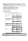
Please supply and install a one piece, air to air reverse cycle air conditioning system.
The system shall be completely assembled, tested and have a complete refrigeration charge ready for
installation and operation from the factory.
The system shall operate at outdoor ambient temperatures as high as 46˚C.
The system shall have a total cooling capacity of kW or greater with an indoor air quantity of
L/s at ˚C db and ˚C wb entering indoor coil temperature with a ˚C temperature
entering
the outdoor coil.
The system shall have a sensible heat capacity of kW or greater with a room db temperature of
˚C.
The total heating capacity (without electric element heaters) shall be kW or greater at ˚Cdb,
˚C wb outdoor air conditions, with ˚C of indoor air entering indoor coil at ˚C db. One
kW electric heater element (accessory) shall be furnished.
The compressors shall be a welded high efficiency hermetic type with internal vibration isolation and be
equipped with a crankcase heater.
Compressors shall be protected by a factory installed anti-cycle device and provide a 3 minute delay before
compressor can restart.
Coils shall be of non-ferrous construction with mechanically bonded aluminium plate fins. Outdoor coils
shall be made, of 9.52mm OD, 0.35mm thick seamless copper tubes mechanically bonded to 0.12mm thick
aluminium plate fins.
Coils with multiple stage refrigeration systems shall consist of independent circuits. Face area of the coil
shall not be less than M
2
. The coil shall be factory pressure and leak tested at 3,233 kPa pressure.
The indoor coil face area shall be not less than M
2
.
Multi-wing propeller type fans shall be fitted at the condenser and shall be dynamically balanced, to ensure
smooth airflow and shall discharge vertically and be direct driven by a weatherproof three phase squirrel
cage kW induction motor.
The system shall be factory wired and all electrical wiring must comply with the Local wiring code. (Controls
and control wiring shall be supplied by the contractor). Compressors and fan motors shall have both internal
and current sensitive overload devices.
An automatic defrost control shall be included to accomplish defrosting (only if required) every
minutes for a period of minutes.
A low voltage transformer (24V) shall be factory installed in the unit for an external control circuit.
High pressure switch (pre-set) shall be factory installed.
The enclosure shall be a single, enclosed, weatherproof casing constructed of phosphatised, zinc coated
steel with acrylic resin primer and ivory white baked enamel finish.
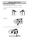
The unit shall be provided with hoisting plates for rigging and hoisting the unit. The hoisting plates shall be
located in the base of the unit.
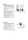
The unit shall have a 25mm OD male drain connection provided. The drain pipe shall be accessible from
either the left or right side of the unit. A blanking cap shall be provided to cap the drain outlet not being
used.
The duct (field supply) shall be fully insulated with fiber glass insulation to prevent sweating and to minimize
sound.
Each unit shall have a drain pan of 1mm thick steel coated with epoxy resin enamel.
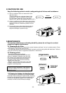
The enclosure shall have openings provided for power connections. Access for both service and installation
shall be provided to compressors, control wiring, filters, electric heaters (when fitted) and fans.
Side panels and top panels shall be removable for easy service access.
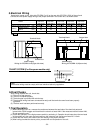
The unit maximum dimensions shall be : height: mm, width: mm and depth: mm.
Due to continuous product development, these guidelines are subject to change.