


- 36 -
FZ0
X3
X1
2
GL
MF1
52
C2
52
C1
21
S41
21
S42
52
F
TM
CZ1
CZ2
FZ1
HZ
X4
X2
CZ2
FZ1
63
H2
51F3
3
1
51
26
C2
L2
CZ2-2
CZ1-2
30
FZ0
50Herts
380~415Volt
3Phase
Power supply
CH2
CH1
PRH-15YA
PRH-15YA-L
···100A
PRH-20YA
PRH-20YA-L
···125A
TM
(3MIN)
CZ2-1
30
FZ0
CZ1-1
30
L3
L2
L1
CIRCUIT BREAKER
(FIELD SUPPLY)
CZ2
L1
C1
26
51
1
3
51F2
H1
63
10
CZ2
30
CZ1
30
FZ1
D1
26
26
D3
51F3
51F2
52
52
C1
C2
RL2
RL1
Low
High
CZ2-1
CZ1-1
AC
24V
AC
220~
240V
Tr
HCHC
2345
6
8
97
1
HEAT
COOL
23WA
SWITCH BOX
(FIELD SUPPLY)
F
TB4 12
TB4 12
TB4 13
14
(2SEC)
C2C1
X1
X2
TB4 11
TB5
TB5
X1 X2
X2
26
D2
X4
CZ1
CZ1
SW3
SW2
SW1
52
52
2
30
30
1
2
3
51F1
HZ
HZ
F(3.15A)
F
(3.15A)
52F
51F1
51C1
51C2
52C1
52C2
N
TB1
TB2
TB3
21 22
21 22
21 22
T
TT
S
SS
R
RR
Blue
Black
Black
Black
Black
Black
Black
Black
Black
Black
Black
Black
White
White
White
White
White
White
White
White
White
White
Red
Red Red
Red
Red
Red
Red
Red
Red
Red
Red
Red
Red
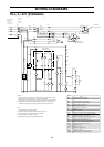
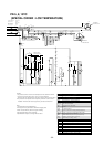
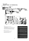
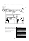
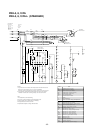
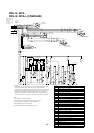
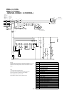
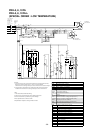
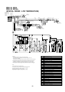
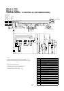
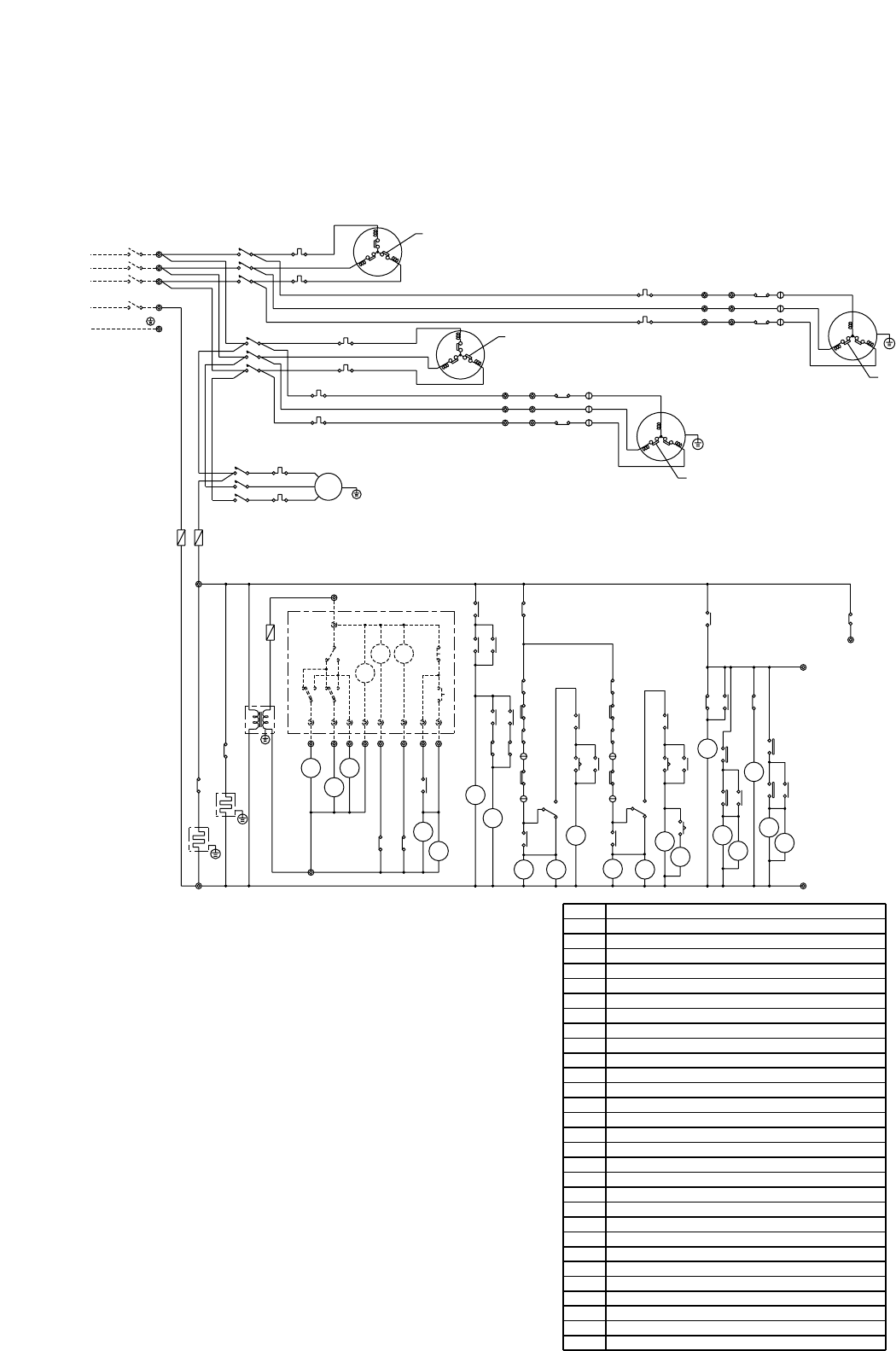
Note:
1.The dotted lines show field wiring.
2.The figure in the parentheses show field supply parts.
3.Color of earth wire is yellow and green twisting.
4.Not specified color of wire is brown.
5.Specification subject to change without notice.
Caution,
1.To protect each Fan motors and Compressors from abnormal current,
these Over current relays<51C1,2>,<51F1,2,3>are installed.
Therefore,do not change factory set value of these Over current relays.
2.To protect the compressors from frequently "ON-OFF" ,timer<TM>is
installed. Therefore,do not change factory set value of this timer.
3.This timer<2>installed so that two compressors may never start at
the same time. The unit stop if the set value of the timer is changed.
INTERNAL
PROTECTOR
MF2
MF3
INTERNAL
PROTECTOR
MC1
INTERNAL
PROTECTOR
INTERNAL
PROTECTOR
MC2
C1
52
1
2
3
11 12
11 12
12
T
S
R
X3
11
Black
CZ1-2
30
CZ2-2
30
30
TM
(3MIN)
C2
52
26
D4
Thermostat(freeze protection)
26L1·2
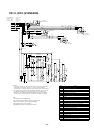
Name
F
51C1·2
Tr
CH1·2
52F
51F1~3
52C1·2
MF2·3
MF1
MC1·2
26D1~4
63H1·2
TB1~5
Fan motor (in door)
Fuse
Transformer
Crankcase heater
Contactor (fan I/D)
Over current relay (fan I/D,O/D)
Contactor (compressor)
Fan motor (out door)
Over current relay(compressor)
Thermostat (defrost)
High-pressure switch
Terminal block
4-Way valve
Thermostat (room temp.)
Timer (anti short cycle)
Timer
Lamp (operation)
Lamp (check)
<23WA>
<RL1·2>
<GL>
TM
2
FZ0·1
21S41·42
<SW1>
<SW2>
<SW3>
30CZ1-1,2
HZ
CZ1·2
X1~4
Switch (operation mode)
Switch (off)
Switch (on)
Auxiliary relay (check)
Auxiliary relay (heater)
Auxiliary relay (compressor)
Auxiliary relay (fan)
Auxiliary relay (defrost)
Symbol
Compressor motor
30CZ2-1,2
Auxiliary relay (check)
PRH-15, 20YA
PRH-15, 20YA-L (STANDARD)