


30
CZ
30
CZ
52C
30
CZ
C
FZ4
FZ3
52
F1
MF1
21
S4
52
F2
52
F4
52
F3
FZ2
FZ1
X1
X2
CZ
HZ
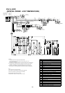
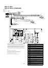
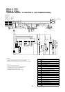
Surge absorber circuit board
DSA
Thermistor(room temp)
TH5
Remote controller
R/C
FZ2~4
Auxiliary relay(fan O/D)
52F2~4
Contactor(fan O/D)
4-Way valve
Thermistor(pipe)
Indoor board
(compressor)
Over current relay
FZ1
Auxiliary relay(check)
Auxiliary relay(heater)
Auxiliary relay(compressor)
Auxiliary relay(fan)
Thermostat(defrost)
High-pressure switch
Terminal block
Auxiliary relay(defrost)
Fuse
Transformer
Crankcase heater
Contactor(fan I/D)
Over current relay(fanI/D,O/D)
Contactor(compressor)
Fan motor(outdoor)
Fan motor(indoor)
Compressor motor
21S4
TH2
IB
30CZ
HZ
CZ
26D1~4
63H
TB1~4
51C
X1·2
Tr1·2
F
CH
52F1
51F1,2,3
52C
MF2
MF1
MC
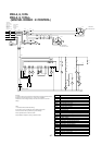
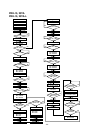
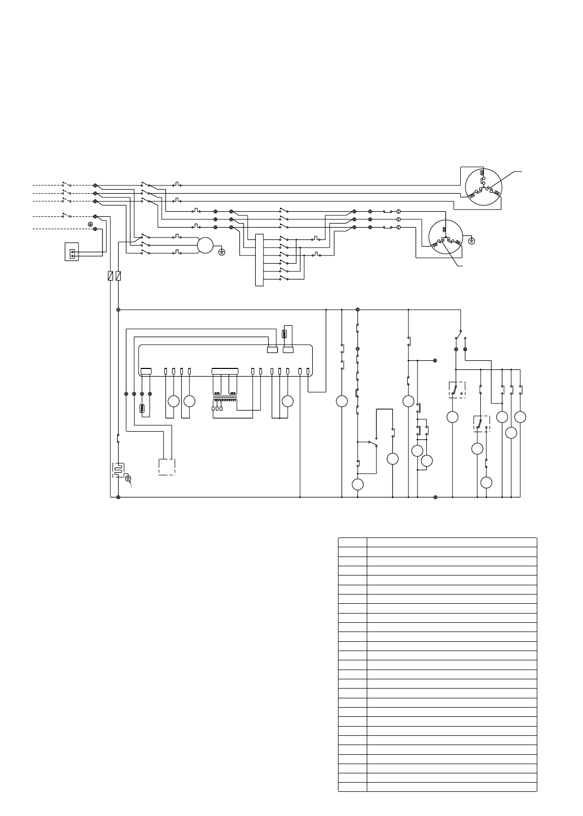
Name
Symbol
15
11
12
16
HZ
14
51F3
TB4
DCBA
Green/Yellow
Blue
DSA
CN
3
1
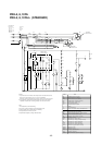
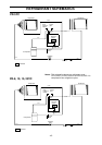
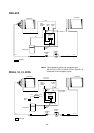
PRH- 10YA
PRH-10YA-L
···60A
PRH- 8YA,
PRH- 8YA-L
···50A
CIRCUIT BREAKER
(FIELD SUPPLY)
CZ
FZ1
CH
51F1
51F2
White
51F2
51F3
R/C
TH5
51
63H
3
FZ
FZ
2
Tr1
52F4
52F3
R
S
T
TB2
1
1
1
X1
2
T
2
S
2
R
TB2
T
2
S
2
2
R
52F2
Black
Black
Black
White
White
Red
Red
Red
3
2
1
TB3 13
TB3 12
TB3 11
T
S
R
4
FZ
2
FZ
3
FZ
26D4
26D3
X1
D2
26
26
D1
X2
FZ1
HZ
TH2
Tr2
IB
52C
F(3.15A)
52F1
51F1
51C
52C
N
PE
50Hertz
380~415Volt
3Phase
Power supply
L3
L2
L1
TB1
1
1
1
Black
Black
Black
Black
White
White
Black
Red
Red
RedRed
Blue
White
Red
MF2
INTERNAL
PROTECTOR
MC
INTERNAL
PROTECTOR
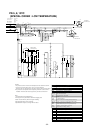
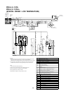
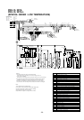
Note:
1.The dotted lines show field wiring.
2.The figure in the parentheses show field supply parts.
3.Color of earth wire is yellow and green twisting.
4.Not specified color of wire is brown.
5.Specification subject to change without notice.
Caution,
To protect each Fan motors and Compressor from abnormal current,
these Over current relays<51C>,<51F1,2,3>are installed.
Therefore,do not change factory set value of these Over current relays.
PRH- 5YA,
PRH- 5YA-L
···40A
8,10YA,YA-L ONLY
- 40 -
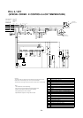
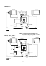
PRH-5, 8, 10YA
PRH-5, 8, 10YA-L
(SPECIAL ORDER : K CONTROL & LOW TEMPERATURE)