


- 53 -
TN-NET SYSTEM (For European models only)
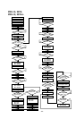
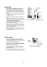
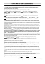
6.Final Checks
After having installed the unit, check that:
(1) The unit is fixed securely.
(2) The unit is installed properly.
(3) The drain pipe is provided with a drain trap.
(4) The electrical wiring has been connected correctly and the terminal screws have been properly
tightened.
(5) The duct work has been performed correctly.
7.Trial Operation
(1) Before turning the unit on, measure the resistance between the terminals of the electrical parts and
ground with a 500V megger and check that the value is at least 1MΩ. If the measured value is below 1MΩ,
do not operate the unit.
(2) Check the operation of the high pressure switch by activating it. Operation should stop when the two leads
of the outdoor unit fan motor are removed from the contactor and cooling continues for 5~10min.
(3) Check that the indoor and outdoor fans are rotating in the proper direction.
(4) After having checked the above points, proceed with a trial operation of the unit.
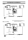
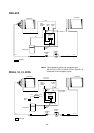
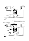
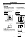
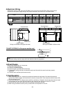
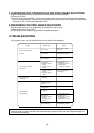
5.Electrical Wiring
Remove the panel on the right side (PR,PRH-5 10) or the rear side (PR,PRH-15,20) of the unit and
connect the units power supply wiring to the proper terminals in the control box, as shown below.
Wiring for PR,PRH-15,20(rear view)
power supply
Control box
Terminal block
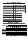
MODEL
INDOOR FAN MOTOR OUTPUT
WIRING
POWER SUPPLY
EARTH
MAIN SWITCH
<kW>
<
mm
>
<
mm
>
< A >
2
2
PR-5YC
PRH-5YA
PRH-5YA-L
PR-8YC
PRH-8YA
PRH-8YA-L
PR-10YC
PRH-10YA
PRH-10YA-L
PR-15YC
PRH-15YA
PRH-15YA-L
PR-20YC
PRH-20YA
PRH-20YA-L
0.75 1.1
5.5
5.5
40
1.1 1.5
5.5
5.5
50
8
8
60
22
22
100
3.0 4.0
22
22
100
1.5 2.2 2.2 3.0
Std.
L1
L2
L3
N
PE
Note:
All electrical wiring must be comply with local electrical authority regulations.
Wiring for PR,PRH-5 10(right side view)
power supply
Control box
Terminal block