


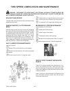

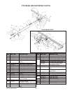

ROLLER CHAIN DRIVES
All roller chain drives are tensioned by automatic spring
loaded tension blocks.
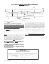
RANGE CONTROL CLUTCH ADJUSTMENT
With the Range control lever set to “NEUTRAL,” the slid
-
ing splined jaw clutch should be at midspan between the
“LO” and “HI” sprocket clutch jaws on the splined gear
cluster shaft. Neither “LO” nor “HI” should be engaged.
When the lever ismoved to “LO”, the engaging jaw clutch
should mate with the “LO” range sprocket clutch and
have about 1/16" of clearance. Likewise for the “HI”
range when the lever is moved to “HI.” This engagement
is adjusted by changing the length of over-lap on the two,
slotted hole linkage bars. See Lubrication Diagram,
page 24 for location - A2.
NOTE: Pending sprocket tooth wear, the two clutch
sprockets and the sliding splined jaw clutch can be
switched from left to right and right to left on the splined
gear cluster shaft to access new wear on opposite sides
of jaw shoulders.
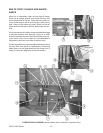
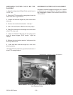
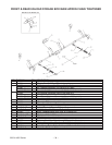
VARIABLE SPEED BELT REPLACEMENT
1. Shift the Variable Speed control lever to “NEUTRAL”
(up).
2. Shift theRange control lever to“NEUTRAL” (center).
3. Move the Independent Outfeed Clutch control lever to
“STOP” (up).
4. Lower the Fold Down Cross Conveyor Extension. If
machine is equipped.
5. Open cluster shield plastic door.
6. Roll the old belt counter-clockwise off of the top
sheaves starting at the 2:00 position.
7. Install the new belt around the lower sheaves and
then roll clock-wise onto the top sheaves starting at the
10:00 position.
8. Close and securely fasten the cluster shield plastic
door.
9. Raise and latch the Fold Down Cross Conveyor Ex
-
tension. If machine is equipped.
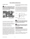
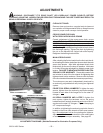
VARIABLE SPEED CONTROL ADJUSTMENT
When the Variable Speed control lever is in “NEUTRAL,”
neither the main aprons nor the unloading augers are to
operate when under load
- (when wagon is full of for
-
age). Variable speed operation should begin when the
lever is moved down one or two notches from “NEU
-
TRAL.” To adjust the drive belt, follow these steps:
1. With the Variable Speed control lever in “NEU
-
TRAL,” remove the drive belt as described under
Variable Speed Belt Replacement.
2. Move the Variable Speed control lever down to
the 2nd from last notch on the control quadrant.
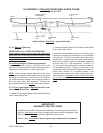
3. Check lower sheaves engagement:
A. If bases of sheaves do not set tight together:
See step #4 (A)
B. If bases of sheaves bottom-out TOO tight to
-
gether: See step #4 (B)
4. Loosen jam nut and remove bolt from the control
rod special bolt and swivel eyelet assembly:
A. Lengthen or unthread the eyelet to set base of
sheaves tight together.
B. Shorten or thread the eyelet to set base of
sheaves tight together.
5. Reinstall bolt into control rod special bolt and
swivel eyelet assembly, and tighten jam nut.
6. Check adjustment made by creating moderate
tension on the Variable Speed control lever when
moving lever between 2nd to last notch and last
notch on the control quadrant.
7. Place Variable Speed control lever into “NEU
-
TRAL,” and reinstall the drive belt as described un
-
der Variable Speed Belt Replacement.
NOTE: The Variable Speed belt should be REPLACED
when sheaves are correctly adjusted and the Variable
Speed control lever does not engage the unloading au
-
gers until the 5th or 6th notch down on the control quad
-
rant.
3200 & 4200 Series -- 28 –