


Mercur
y
6-5 Stat
–
Installation & User Guide
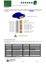
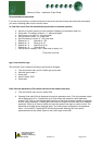
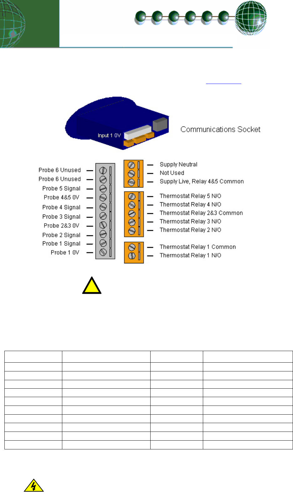
Connections
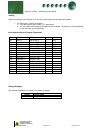
All connections are made to the back of the controller. The diagram below shows the connection detail. Inputs
and outputs are assigned according to the chosen configuration. See
Specification for further details on
connections.
!
Do not connect an earth.
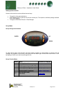
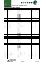
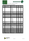
Input/Output Allocation Tables
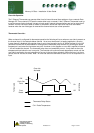
An over-ride can be achieved by switching in a fixed value resistor in parallel with the probe inputs as shown
in the table below.
5 Ch Thermostat Description Alarm Action (Switched Resistor)*
Input 1 Probe 1 and Over-ride 1 Yes Over-ride signal 1
Input 2 Probe 2 and Over-ride 2 Yes Over-ride signal 2
Input 3 Probe 3 and Over-ride 3 Yes Over-ride signal 3
Input 4 Probe 4 and Over-ride 4 Yes Over-ride signal 4
Input 5 Probe 5 and Over-ride 5 Yes Over-ride signal 5
Relay 1 Thermostat Channel 1 N/A
Relay 2 Thermostat Channel 2 N/A
Relay 3 Thermostat Channel 3 N/A
Relay 4 Thermostat Channel 4 N/A
Relay 5 Thermostat Channel 5 N/A
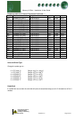
* For PT1000 probes use 820 Ohm
Ensure that all power is
For NTC2000 and NTC2k25 probes use 590 Ohm
switched off before
installing or maintaining
this product
Revision 1.2 Page 4 of 21