


9
Majestic Fireplaces® NVB Series B-Vent
7412950
U.S.: Consult the current National Fuel Gas Code,
ANSI Z223.1
Canada: CSA - B149.1 installation code.
Test for leaks. Use a 50/50 solution of liquid soap and
water to test for leaks at gas fittings and joints. Apply
water/soap solution with brush only -
do not over
apply. NEVER
test with an open flame.
The gas control is equipped with a captured screw
type pressure test point, therefore it is not necessary
to provide a 1/8" test point up stream of the control.
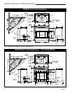
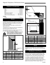
When using copper or flex connector use only ap-
proved fittings. Always provide a union so that gas
line can be easily disconnected for burner or fan
servicing. See gas specification for pressure details
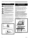
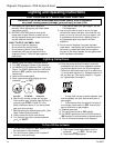
and ratings. NOTE: If flex connector is used, it must be
kept inside of the appliance. (Fig. 8)
FP598
Fig. 8 Typical gas supply installation.
1/2" Gas Supply
1/2" x 3/8" Shut-off Valve
3/8" Union
3/8" Nipple
3/8"
Nipple
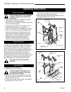
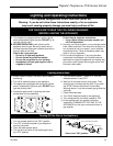
Remote Wall Switch
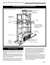
1. Thread wire through the electrical knockout located
on side of unit. Do not cut wire or insulation on metal
edges. Ensure that wire is protected. Run the other
end to a conveniently located wall receptacle box.
2. Attach wire to switch and install switch into recep-
tacle box. Attach cover plate to switch.
3. Connect wiring to gas valve. Refer to Figure 9 or 10.
CAUTION: Do not wire millivolt remote
wall switch for gas appliance to a 120v
power supply.
For lighting instructions, see Page 14.
R Models