


8
Majestic Fireplaces® NVB Series B-Vent
7412950
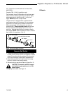
Parts Identification and Chase Installation
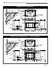
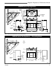
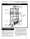
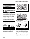
Fig. 7 Parts identification and system installation.
(Insulation methods shown are optional for cold climate,
not a requirement for unit operation.)
FP597
*Do not install header
until unit is in place.
See Page 8, "Mounting
the Appliance."
Termination Cap
Storm Collar
Pan Flashing
Draftstop
Firestop
Standoff
Nailing Flange
Electrical
Access
Outside Air
Cover Plate
Surround
Batt Insulation
(cut out around
firestop)
Screen
Grate
Firebox
Ceiling Level
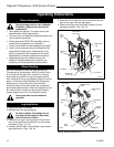
Gas Line Installation
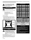
This appliance must be isolated from the gas supply
piping system by closing its individual manual shut off
valve during any pressure equal to or less than 1/2 psig
(3.45 kPa).
The appliance and its individual shutoff valve must be
disconnected from the gas supply piping system during
any pressure testing of that system at test pressures in
excess of 1/2 psig (3.45 kPa).
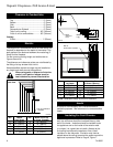
If gas piping from the source to the appliance location
has not been accomplished, install the required pipe.
Consult local plumbing code to assure proper pipe size.
The gas pipeline can be brought in through the right
side of the appliance. A knockout is provided to allow
for the gas pipe installation and testing of any gas
connection. It is most convenient to bring the gas line
in from the right side, as this allows fan installation or
removal without disconnecting the gas line.
NOTE: The gas line connection can be made with 3/8"
copper tubing approved for propane or natural gas, 1/2"
rigid pipe or an approved flex connector, then reduced
to 3/8" to the appliance. Because some municipalities
have some additional local codes, it is always best to
consult your local authority.