


6
Majestic Fireplaces® NVB Series B-Vent
7412950
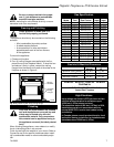
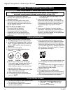
Clearance to Combustibles
Appliances
Top .......................................................... 0” (0mm)
Bottom .................................................... 0” (0mm)
Side ........................................................ 0” (0mm)
Back ........................................................ 0” (0mm)
Perpendicular Sidewall ........................... 0” (0mm)
Top of unit to ceiling .......................... 36” (914mm)
Front of unit to combustibles ............ 36” (914mm)
Venting
B-Vent ................................................... 1” (25mm)
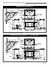
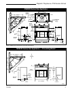
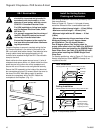
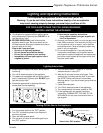
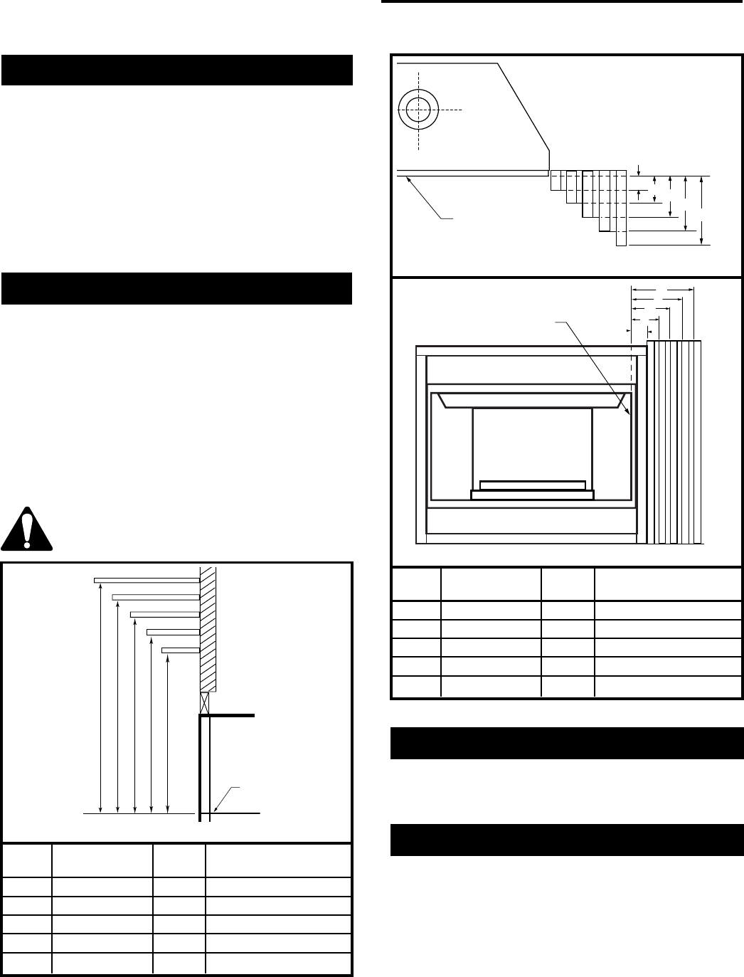
Mantels\
The height that a combustible mantel is fitted above the
fireplace is dependent on the depth of the mantel. This
also applies to the distance between the mantel leg (if
fitted) and the fireplace.
For the correct mounting height and widths refer to
Figures 5a and 5b
The distances and reference points are not affected by
the fitting of a bay window front trim kit.
Noncombustible mantels and legs may be installed at
any height and width around the appliance.
When using paint or lacquer to finish the
mantel, such paint or lacquer must be
heat resistant to prevent discoloration.
J
F
G
H
I
Mantel
Leg
O
N
M
L
K
Ref. Mantel Ref. Mantel Leg From
Leg Depth of Comb. Opening
F 14" (356mm) K 14" (356mm)
G 12" (305mm) L 12" (305mm)
H 10" (254mm) M 10" (254mm)
I 8" (203mm) N 8" (203mm)
J1¹⁄₂" (38mm) O 1¹⁄₂" (38mm)
Black
Surround
Face
CFM164
CFM170
Fig. 5b Combustible mantel leg minimum installation.
Side of
Combustion Chamber
Hearth
A hearth is not mandatory but is recommended for
aesthetic purposes. We recommend a noncombustible
hearth.
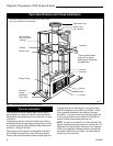
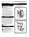
Insulating For Cold Climates
When an appliance is installed in a chase or an outside
wall, the enclosure should be insulated like any other
wall of the home. Insulation should be installed under
the appliance and on the inside of the exterior walls.
In a chase, it is a good idea to install a firestop at the
first ceiling level above the appliance. Also, install
insulation on the side walls. Insulation may then be
placed above the ceiling to assure the space around the
appliance is protected. Refer to Page 8, Figure 7.
Ref. Mantel Ref. Mantel From Top
Shelf Depth of Comb. Chamber
V 14" (356mm) A 18" (457mm)
W 12" (305mm) B 16" (406mm)
X 10" (254mm) C 14" (356mm)
Y 8" (203mm) D 12" (305mm)
Z1¹⁄₂" (38mm) E 8" (203mm)
CFM146
ABCDE
V
W
X
Y
Z
Fireplace
Top of Combustion
Chamber
Fig. 5a Mantel clearances.
Side View