


21
Majestic Fireplaces® NVB Series B-Vent
7412950
Optional Accessories
Fan Kit
The FK12 fan kit is available for use on the NVBC36
and NBVC42 model appliances only.
Auxiliary fan systems increase the efficiency of the
circulation of the heating air. The FK12 fan assembly is
a fixed speed fan system and does not allow for vari-
able speed control.
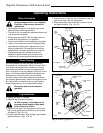
Installation
Remove the 2 ceramic fiber refractory panels by
carefully lifting them out of the fireplace. Next, remove
the access panel by pulling it up and out from the side
edge of the panel. Use caution — the panel edges may
be sharp.
Center the fan assembly over the mounting location
and secure it with the Velcro
®
strips at the back of the
fireplace.
Insert the plug into the receptacle (EB1) located
against the lower right side wall of the fireplace.
Caution: Be sure that no wires are pinched.
Prior to reinstalling the access panel and the hearth
brick, it is advisable to operate the wall switch on and
off to assure fan operation. If the fan does not operate
and you are assured that 115 VAC power is present at
the receptacle, contact your Dealer.
Reinstall the access panel and hearth brick by revers-
ing Step 1.
WARNING: Never contact blower wheels during
operation.
Speed Control
The SCVS variable speed control is available to allow
speed adjustment of the fan.
Electrical Connection
The EB-1 electrical junction box is available for use with
the fan kits. The EB-1 is standard on the electronic
ignition models.
Glass Doors
Bi-fold and single panel glass doors are available to
enhance the viewing of the fireplace.
Appliance Models Glass Doors
NVBR36/NVBC36 36GSKBB
36GDKBB
36GDKBK
36GDKDP
36GDKS
Appliance Models Glass Doors
NVBR42/NVBC42 42GSKBB
42GDKBB
42GDKBK
42GDKDP
42GDKS
Outside Air Kit
The Model AK-MST Outside Air Kit is designed to bring
additional combustion air directly from the outside to
the fireplace. Refer to installation instructions provided
with the Outside Air Kit.
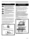
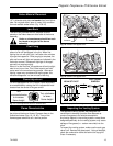
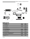
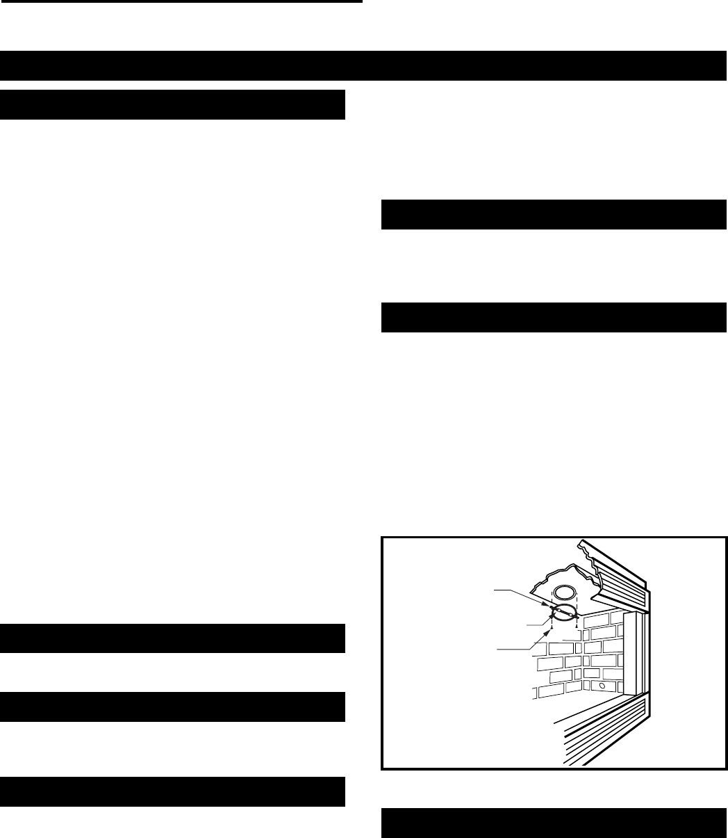
Thermal Vent Damper
Installing the TVD6/7 Thermal Vent Damper reduces
cold air infiltration when fireplace is not in use by
opening and closing automatically.
Attach the thermal vent damper to the combustion
dome with 2 screws. Be sure the tab points down. (Fig.
21)
Start the appliance and operate it for approximately 5
minutes. Turn the unit off and check if the vent damper
is in the open position (blades down from the horizontal
position). If the damper has not opened, check installa-
tion.
Fig. 21 Attach the thermal vent damper.
FP577
Tab
Thermal Vent Damper
Screws
Remote Controls
Optional remote control units are available to control
different functions of the appliance.
Model Function/s Controlled
MRC1 “ON/OFF”
MRC2 “ON/OFF” and Temperature
MRC3 “ON/OFF” and Temperature control
with a digital and a programmable 24
hour clock