


10
Majestic Fireplaces® NVB Series B-Vent
7412950
EB-1 Electrical Box
The fireplace, when installed, must be
electrically connected and grounded in
accordance with local codes or, in the
absence of local codes, with the current
CSA C22.1 Canadian Electrical Code.
For USA installations, follow local codes
and the National Electrical Code, ANSI/
NFPA No. 70.
It is strongly suggested that the wiring of
the EB-1 electrical junction box be car-
ried out by a licensed electrician.
Ensure that the power to the supply line
has been disconnected before commenc-
ing this procedure.
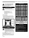
Once the fireplace is secured, complete wiring the fan
kit. Remove knockout in the center of the back of the
EB1 and install listed cable clamps. Feed electrical wire
through cable clamp leaving approximately six (6)
inches of wire exposed through the EB1. Secure cable
clamp to the wire.
Attach white wire from power source to one (1) wire of
receptacle and secure with a nut. Attach black wire from
power source to the other wire of the receptacle and
secure with a nut. Be sure nuts are tightened securely.
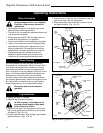
Secure the EB1 assembly to the inside of the electrical
box coverplate using two (2) screws. Attach the cover to
the face of the EB1 while being careful to position
excess wire completely within the EB1. Attach the
coverplate to the fireplace. (Fig. 11)
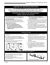
Fig. 11 Junction box (EB-1) hook-up.
FP580
Outside
Electrical Box
Front Of Unit
Inside
Front O
f U
nit
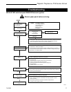
Install the Venting System,
Flashing and Termination
See venting installation instructions provided by the B-
Vent manufacturer.
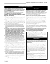
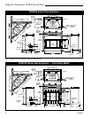
Refer to Pages 4-5, Figures 1-4 to locate chimney
centerline dimension from a combustible back wall.
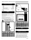
• Minimum vertical chimney height — 12 feet (3.65m).
• Maximum vertical height — 40 feet (12m).
• Minimum height with two 90° elbows — 16 feet
(4.06m)
• Elbow requirements allow a maximum of two
90 degree elbows or four 45 degree elbows
per installation. (Two 45 degree elbows =
One 90 degree elbow.) See venting chart for
proper elbow offset runs. Use Table 4 for NVB36/42
installations when not installing the GSKBB Single
Panel Glass Door. Use Table 5 for NVB36/42 instal-
lations when installing the GSKBB Single Panel
Glass Door.
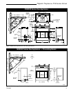
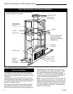
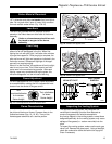
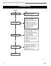
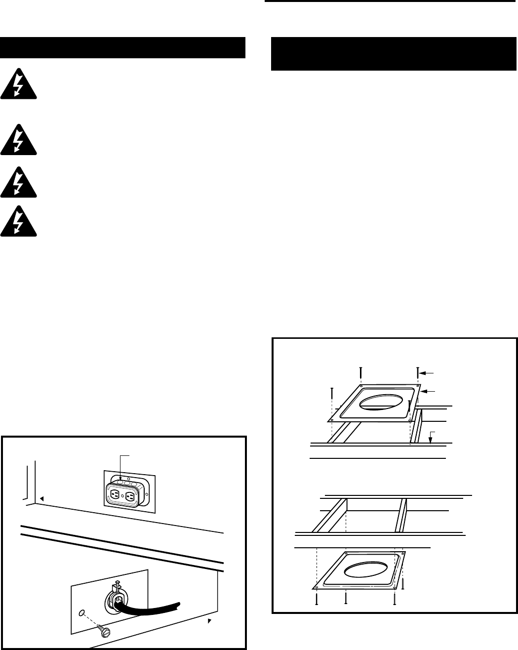
For firestop positioning, refer to Figure 12. Only one (1)
firestop required per frame. NOTE: A firestop is not
required at the roof.
Fig. 12 Firestop/draftstop positions.
Ceiling Installation
Attic Installation
Firestop position when area above ceiling is an attic.
Firestop position when area above ceiling is NOT an attic.
(Firestop/draftstop
appearances may
vary. Only 1 firestop
required per frame.)
Firestop
Spacer
Nails (4)
Joist
FP384