


7
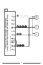
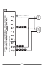
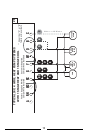
• All of the dashed wires shown in the following wiring
diagrams are either optional, or their usage depends upon
your specific system type or brand. For example: Diagram
#1 shows the fan wire as optional. If your system does not
have a fan, than this terminal will not be used.
• The optional “C” terminal is used for powering the
thermostat by the 24 Volt system power. This can be used
alone, or in addition to installing batteries.
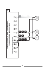
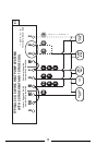
• If “Y” and “C” wires are both present, then “C” is most
likely a system common wire.
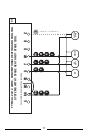
• For Heat Pump systems, use either the “O” terminal or the
“B” terminal, but not both. If an “O” and a “B” wire are
both present, “B” is likely a system common and may be
connected to the “C” terminal. Connecting system
common power to this thermostat’s “B” terminal may
damage the thermostat, and also your system.
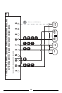
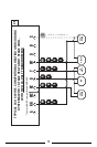
• If replacing a Honeywell TM-11, tape off the “R” wire.
Connect the “B” wire to the “RH” terminal.
• If replacing an old thermostat that has a mechanical clock,
there may be two
wires labeled as “C” for the clock power.
Tape off these wires and do not connect them to the “C”
terminal of this thermostat.