


3.6 Reset-buttons
'Panel reset'-button: All actual fire alarms, technical messages, fault alarms, faults and actuations are
reset in one action on the control panel by pressing this button. With a fire detection control panel
BCnet216 this function effects the entire control panel, irrespective of the BCnet sectional control
panel on which the button was pressed. For further information see from page 31 in Chapter 4.2.1:
"Resetting the fire detection control panel".
'Silence buzzer'-button: The internal buzzer is silenced by pressing this button. With a fire detection
control panel BCnet216 the internal buzzers of all BCnet sectional control panels are silenced, irre-
spective of the BCnet sectional control panel on which the operation was made. This button has the
additional function of activating the display test. (See page 44 in Chapter 4.7.12.2: "Testing the op-
tic and acoustic displays and the buzzer - submenu point [Display test]").
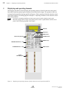
3.7 Light-emitting diodes displays
The illumination of one of the light-emitting diodes indicates a current event. Detailed information is
shown on the LC-display, or - if several events occurred simultaneously - can be displayed separately.
Notice that area filters may be parameterized for BCnet sectional control panels of a fire detection
control panel BCnet216 which suppress the output of various information on the corresponding BCnet
sectional control panel.
'Actuation activated' (red): Is illuminated if one or more actuations, transmitting devices or alarming
devices are activated. See page 55 in Chapter 5.3: "Activation condition of actuations".
'Technical message' (yellow): Is illuminated if one or more technical messages of corresponding de-
tectors have arrived. See page 56 in Chapter 5.4: "Message condition for technical messages".
'Disablement' (yellow): Is illuminated if one or more parts of the system or functions are disabled.
See page 61 in Chapter 5.6: "Disablement condition".
'Test condition' (yellow): Is illuminated if one or more detector zones or elements are in test condi-
tion. See page 63 in Chapter 5.7: "Test condition".
'Energy fault' (yellow): Is flashing in case of a fault in the power supply (power unit, stand-by bat-
tery, etc.). See page 58 in Chapter 5.5: "Fault-message condition".
'System fault' (yellow): Is flashing in case of a fault in the central computer; it is illuminated in case
of a fault of the display and control panel computer.
In order to maintain the most important functions of the control panel or the BCnet sectional control
panels in case of malfunctions of single parts of the control panel, the manufacturer has included
elaborate security-measures that were developed during many years of experience with fire alarm tech-
nology. Nevertheless, a total guarantee for the proper workings of the control panel cannot be given,
especially if two or more faults occur simultaneously!
Observe the Hints given from page 9 in Chapter 1.2.2: "What to do in case of a fault", from page 58 in
Chapter 5.5: "Fault-message condition" and from page 67 in Chapter 6.3: "Reconditioning and
maintenance"!
'Authorization' (green): Is illuminated after entering the code for authorization level 2 (operating the
control panel is possible now) or is flashing after entering the code for authorization level 3 (setting
of parameters is possible now). See page 29 in Chapter 4.1: "Operating authorization".
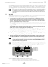
3.8 TRANSM. DEVICE 1 - field
Up to ten independent transmitting devices can be managed by the fire detection control panel
BC216-1 and by every BCnet sectional control panel of the fire detection control panel BCnet216.
They can be parameterized either as primary transmitting device or as transmitting device for fire mes-
sages or as transmitting device for faults.
The function domain "notification of the fire brigade in case of fire" regionally is regulated differently.
Therefore, the following list only presents the most important possibilities of this function domain of
the fire detection control panel Series BC216.
HB216AE.SAM / 0130 / AN9161202
ZN5002/73/25
User Manual Series BC216 / Part A Chapter 3 • Displaying and operating elements
25