


You operate the fire detection control panel Series BC216 with the clear and sturdy keypad on the front
of the case. An illuminated LC-display and light-emitting diodes (LED) are integrated in the keypad as
optical display elements. For acoustic alarming, a loud buzzer is fitted in the case of the control panel.
Event messages of the whole control panel are standardizedly displayed on the displaying elements of
all operable BCnet sectional control panels with the network fire detection control panel BCnet216.
The operating menus are exclusively displayed on the BCnet sectional control panel where the opera-
tion is made.
3.1 Info field
The Info field of the fire detection control panel BC216-1 and every operable BCnet sectional control
panel of the fire detection control panel BCnet216 contains 4 display elements:
Exact information is provided by the LC-display measuring four lines by 20 characters. All mes-
sages about events and menu points for operation and setting of parameters are displayed here by
using text. The messages that are displayed separately on the control panel by using light-emitting
diodes are shown in detail on the LC-display as well.
The display lights up if an event has occurred. In the normal condition (that means, there is no event
and no operating action at the control panel), the illumination is turned off 30 seconds after a button
was pressed last.
30 seconds after the last operating action the display returns to showing the earliest event with the
highest level of priority, no matter what event was displayed last.
The red illuminated display 'ALARM' indicates the condition of a fire alarm. Every message from a
fire detector that is evaluated by the fire detection control panel BC216-1 or BCnet216 as fire alarm,
activates this display and keeps it illuminated until all alarms have been reset.
The yellow illuminated display 'FAULT' indicates the condition of a fault. Every message from a
fault detector or fault, evaluated by the fire detection control panel BC216-1 or BCnet216 as a fault,
activates this display and keeps it flashing until no fault is left.
The green light-emitting diode 'POWER' indicates the sufficient supply of energy to the fire detec-
tion control panel BC216-1 or the corresponding BCnet sectional control panel of the BCnet216.
With the fire detection control panel BCnet216 area filters can be set by the installer for every BCnet
sectional control panel through which only certain messages are processed and displayed on the BCnet
sectional control panel. Basically, all messages are processed and displayed on the BCnet sectional
control panel, defined as main operating unit.
If the light-emitting diode 'POWER' is not illuminated you have to assume that the control panel or the
BCnet sectional control panel is not able to receive, evaluate and transmit messages of detectors due to
a total loss of power, i.e., the mains power as well as the emergency power supply are shut down!
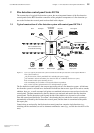
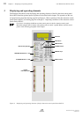
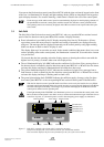
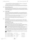
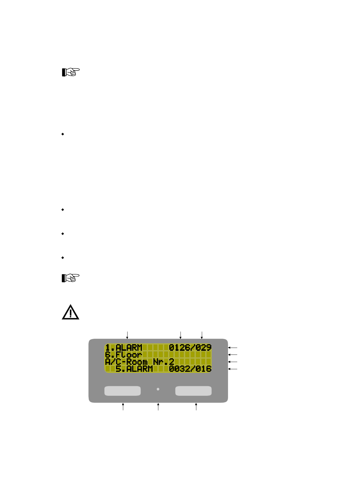
Figure 5: Info-field - exemplary fire alarm with 5 current fire messages
The first line displays the current alarm with the zone and element number.
The second line displays the first text information for the zone of the current alarm.
ALARM FAULT
POWER
Kind of message Zone number Element number
Fire alarm (Nr.1)
Information text 1
Information text 2
Last alarm (Nr.5)
Alarm display Power display
Fault display
HB216AE.SAM / 0130 / AN9161202
ZN5002/73/23
User Manual Series BC216 / Part A Chapter 3 • Displaying and operating elements
23