


All installations and services must be performed by qualified service personnel.
26
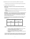
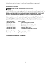
TABLE 2
This gas furnace is equipped with a fixed orifice sized for the manifold pressure shown
on the rating label. The input can only be increased, or decreased, by adjusting the
manifold pressure. Remove the 1/8" threaded pipe plug located on the gas manifold.
Use a U tube manometer or recently calibrated pressure gage to measure the pressure.
To adjust the pressure, remove the screw cap from the regulator on the gas valve and
using the adjustment screw. Decrease the pressure by turning the screw
counterclockwise or increase it by turning the screw clockwise.
?
??
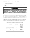
? CAUTION: ADJUSTMENTS TO THE LISTED PRESSURE MUST NOT EXCEED
0.3" WC A 0.3" WC adjustment will increase or decrease the input approximately 4.0%.
Replace screw (cap) when adjustment is complete.
The correct input can be assumed if the furnace manifold pressure is the same as that
shown on the rating label if a gas meter is not available for natural gas or the unit is
installed on an unmetered propane gas supply.
Shut off the gas supply to the furnace. Remove the pressure gage and re-install the
pipe plug using a thread compound resistant to the action of LP gases.
If the rated input cannot be obtained with the present orifice at the correct pressure,
your local gas supplier may assist in sizing the proper orifice. Thermo Products
Engineering Department will gladly assist in sizing the orifice if you provide them with
the heating value in BTU per cubic foot and the specific gravity of the fuel gas.
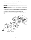
M. BURNER ADJUSTMENT
: The GMD1-80N furnace model utilizes an in-shot burner design that
does not require an air shutter adjustment (air shutters are not used) for proper
flame characteristics. Burner box access cover must always be secured with all
screws in place and tightened before operating furnace.
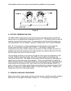
This unit is designed to not require any burner adjustment. The flames should be
checked by looking through the sight glass located on the burner box. Burner flames
should be clear, blue, and almost transparent in color. (See Figure 9). NOTE: It is not
unusual to have mostly blue flames with yellow or orange tips visible in the tube for
propane gas.